WyreStorm 4K Matrix Solutions MX-0808-PP-pOH-4K 4K HDBaseT™ 5-Play™ 8x8 Matrix including PoH, Bidirectional IR and RS232 Serial Control Instruction Manual Thank you for choosing this WyreStorm product. Please read these instructions carefully before installing to avoid complications later. Technical Support: support@wyrestorm.
CONTENTS AND INTRODUCTION Contents 1 Introduction 2 Features 3 Safety precautions 4 Package contents 5 Specifications 6 Front panel description 7 Rear panel description 8 Connection and operation 9 Front panel control 10 Matrix IR remote control i. Matrix control at matrix location (local) ii. Remotecontrol at display location iii. Advanced remote control 11 RS232 control i. Com control software home screen ii. Message receive window iii. Send message window iv.
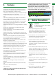
• Protection against ESD (electrostatic discharge) included within the unit to further stabilise transmission. • LED indications for clear power and video signal selection. 2. MX0404-QI Features • Quick and easy installation – set up in seconds straight out of the box. • Simplified ports - Input: HDMI – Output: integrated RJ45 connectors for a single Cat5e/6/7 UTP cable to each display point for ease of installation.
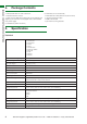
PACKAGE CONTENTS AND SPECIFICATIONS 4. Package Contents 1 x MX-0808-PP-POH-4K main chassis unit 1 x Printed instruction manual 1 x Flash memory USB stick containing PC control software and digital copy of instruction manual (digital version downloadable from product page) 8 x IR Receivers (30KHz to 50KHz) 5.
Cable Specifications Cable Type Range Supported Video Cat5e/6 100m/328ft 1080p @ 60Hz / 36bit Deep Colour 70m/230ft 1080p @ 60Hz / 48bit Deep Colour 1080p @ 60Hz 3D 4Kx2K @ 30Hz / 4:2:2 chroma sub-sampling 100m/328ft 1080p @ 60Hz / 48bit Deep Colour 1080p @ 60Hz 3D 4Kx2K @ 30Hz / 4:2:2 chroma sub-sampling Cat6a/7 FRONT PANEL DESCRIPTION NOTE: Cable types below are for reference only. It is strongly recommended that you use the cables recommended by HDBaseT.
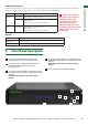
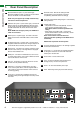
REAR PANEL DESCRIPTION 7. 1 Rear Panel Description Mirrored HDMI OUT ports 1~8 (From left to right) Mirrored to HDBaseT output, connects to the local HDMI devices with HDMI or DVI to HDMI cables. 10 EDID DIP switch - Manual DIP setting for EDID management for improved device connection compatibility. (See EDID section for settings) NOTE: this port supports up to 1080p resolution only.
9.9.
CONNECTION & OPERATION Adjustment of the IR emitter position after installation may be required to achieve the best results as moving to different areas of the source fascia can improve IR performance. Plug the 3.5mm jack of the IR emitter into the corresponding number IR TX port on the rear panel of the MATRIX. NOTE HDMI output supports up to 1080p only. 4K source cannot be duplicated.
OPTIONAL CONNECTION: 1 If using a duplicate display or AVR mirrored to the HDBaseT Output, connect the display via the HDMI OUT port of the transmission card NOTE HDMI output supports up to 1080p only. 4K source cannot be duplicated. 2 For control system integration, connect additional RJ45 terminated category cable or RS232 serial cable.
7 11. Basic Remote Control 2 3 To change handset battery 4 5 7 Set the output 1 to the input 1. 8 i. Press left/right selection button to highlight the Output OUTPUT 1. LED blinks slowly to indicate theOUTPUT output hasINPUT been SELECT INPUT SELECT 1 CHANNEL CHANNEL chosen. 2 1 3 ii. Press up/down selection button to switch that 1Output 4 2 2 to Input 1. 5 OUTPUT take effect. OUTPUT iii.
L OUTPUT CHANNEL INPUT SELECT 1 RS232 For reference: The IR is NEC and possesses a carrier wave of 38KHz with a system code of 0x00 Control control include wyresto 2 OUTPUT CHANNEL 5 INPUT SELECT 6 1 2 Control of the matrix from 2the display location side using 7 11.
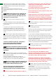
RS232 CONTROL 11. ii) Message Receive Window RS232 Control Serial control of the matrix via RS232 enables third party control systems to be integrated within a MX-0808-PPPOH-4K system. The COMCTL software included with this product communicates via serial to enable advanced matrix features to be accessed, such as relaying system status and additional control of matrix settings, including full configuration of the matrix for optimum performance.
Click Send to view the current condition of all output ports. 3 Click Connect to establish communication with selected Com Port. When a COM Port is connected, the only option will be to Disconnect and vice versa. Note: In Connect Status area: • Connected: indicates that the matrix is connected to the COM port and communication is enabled. • Disconnected: indicates that the matrix is disconnected from the COM port and communication is disabled.
3 Click OK to store the IP address and click exit. to 1 Click EDID SET in Set Panel area. RS232 CONTROL Set a Static IP Address 1 Click IP SET in Set Panel area to allow access to IP functions to obtain and store the IP address. 2 Select an output port from the Port Select area – such as output port 4 in this case. 2 Select Set static IP address to manually input the IP functions if no address appears or if the system is unable to detect an IP address. Enter an IP address (such as 192.168.10.
Next, select an input port in the same Port Select area - such as input port 2 in this case - and click Write to save the current EDID to the selected input port. Wait a few seconds for the process to complete. 1 UTP Long Cable Mode In instances where the distance of the cable may be effecting transmission quality, this setting toggles ON/ OFF to improve display quality.
7 6 5 3 2 INPUT set ge hand To chan ry batte ntro l te Co Remo SELECT Basic 8 7 6 5 4 3 1 OUTP CHAN UT NEL 2 INPUT SELEC T 4K Source Device 0303 IR IR RXRX port port of of matrix matrix with with Launch the COM Control software. IR IR TXTX emitter emitter placed placed securely securely 0202 Click IR MATRIX in Set Panel area.
For reference: The IR is NEC and possesses4 a carrier wave of 5 38KHz with a system code of 0x00 OUTPUT CHANNEL INPUT SELECT 1 0x1d 0x0d 2 0x1b 0x15 3 0x12 0x08 4 0x55 0x4a 5 0x06 0x03 your MX0606/0808-PP.
RS232 CONTROL ADVANCED OPERATION ANCED OPERATION source for Output 4 unreadable. 01 Press to automatically the current IR code from the MX0606/0808-PP Controlread Code device. Output 1 <”08” “09”> 01 resulting in the to 1 ”00” The 2 ”01”the 3code ”02” appears 4IR ”03” ”04”wait ”05”modify 7the ”06”code 8 ”07” A Receives specific code5used to6operate Matrix via section B where output and input code can be edited if remote control. Can contain a custom or data code.
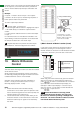
Click Open to connect this COM debug software to the matrix. viii) Controlling the IR Devices Remotely The matrix allows the creation of different IR paths to remotely control the IR devices, such as sources or displays using device remote handsets from the display or source location. Note: 1 Ensure IR receivers are securely connected to correct ports of receiver or matrix and placed in clear view to receive IR signals from device remote handsets.
SingleCat5e/6/7 Cat5e/6/7 Single 70m/230ft 70m/230ft IR Path IR Path HDMIInput Input1 1 HDMI This is accomplished by placing a series of IR Emitters on devices TX1 1 IRIRTX to control HDMIInput Input2 2 and Receivers at all locations you wish to control from to HDMI enable the IR signal to travel both ways via the single Cat5e/6/7 TX2 2 IRIRTX HDMIcable.
NOTE Depending on the settings of the incoming source content a delay may still exist where resolution between screen and source requires negotiation, but EDID is still communicated as normal when this the QuickSync feature is enabled. This feature is NOT enabled out of the box and must be manually activated within the COM CTL software. see page 15. 12.
UP denotes ON. LAN CONTROL AND TROUBLESHOOTING EDID Switches that are marked in grey indicate the switch can be in any position. Before copying output port EDID, ensure the matrix port is connected to a display - EDID copy will fail without connection to output device. Matrix must be restarted for changes to DIP switch to take effect. 14.
6) Correct connection – It may seem obvious but double check all UTP, HDMI, power and IR cables are connected to the correct ports. NOTE Even a fraction off can be the difference between a perfect picture and a blank screen. Double check all connections are firmly made in the correct ports.
FAQ NOTE Occasionally with some sources, the device settings allow the specification of audio output through a TV or an HDMI port. If using an AV receiver, check the HDMI output option is selected. 3) Do all the local sources work through the AV receiver? Check the operation of each source individually. Bandwidth 1) If using a graphics-based source (such as a PC/Mac/ media server), make sure the source resolution is set to a maximum of 4096x2160p 30Hz.
What about 3D? The RX-70-4K, all of our matrix switches and most of our extender products will pass-through a 3D Blu-ray signal (frame packing - Blu-Ray & Stereoscopic - satellite/cable). How do I control the sources? All of our HDMI distribution products support IR passthrough from point-to-point extender sets to AMP and HDBaseT matrices. Most of the range now supports wideband IR meaning it is compatible with any IR device available on the market.
, PROVIDED SERVICE ,MAIL-IN-SERVICE, WARRANTY AND WARRANTY LIMITS & EXCLUSIONS 17. Provided Service 19i. Warranty 1. Damage requiring service: This unit should be serviced by a qualified service personnel if: • The DC power supply or AC adaptor has been damaged. • Objects or liquid have gotten into the unit. • The unit has been exposed to rain. • The unit does not operate normally or exhibits a marked change in performance. • The unit has been dropped or the cabinet damaged.
GLOSSARY 2. There are no express warranties except as listed under “limited warranty coverage.” The warrantor is not liable for incidental or consequential damage resulting from the use of this product or arising out of any breach of this warranty. For example: damages for lost time, the cost of having a person/persons remove or re-install previously installed equipment, travel to and from service location, loss of or damage to media, images, data or other recorded/stored content.
19. Reference Logs INPUT INSTALLATION REFERENCE LOGREFERENCE LOGS 21. Installation Reference Log - Input Reference Log Wyrestorm Matrix INPUT installation reference log INPUT Input number on Matrix Source Location Source Details Source resolution & audio settings Cable Number 1 2 3 4 5 6 7 8 27 28 Technical Support: support@wyrestorm.com US: +866 677 0053 EU: +44 (0) 1793 230 343 Technical Support: support@wyrestorm.
OUTPUT REFERENCE LOG Installation Reference Log - Output Reference Log OUTPUT Output number on Matrix Output Location Display Details Display Resolution & Audio Settings Cable Number 1 INSTALLATION REFERENCE LOGS 21. Wyrestorm Matrix OUPUT installation reference log 2 3 4 5 6 7 8 Technical Support: support@wyrestorm.com US: +866 677 0053 EU: +44 (0) 1793 230 343 Technical Support: support@wyrestorm.
INSTALLATION NOTES 22. Installation Notes 30 Technical Support: support@wyrestorm.
INSTALLATION NOTES Technical Support: support@wyrestorm.
www.wyrestorm.com WyreStorm Offices US Office: 6991 Appling Farms Parkway, Suite 104, Memphis, TN 38133 Tel: + 901 384 3575 Fax: + 901 384 3574 Unit 22, Ergo Business Park, Swindon, Wiltshire, SN3 3JW UK Tel: +44 (0) 1793 230 343 Fax: +44 (0) 1793 230 583 WyreStorm Technical Support US: +86 6677 0053 UK:- +44 (0) 1793 238 338 Email: support@wyrestorm.com We reserve the right to change specification or product dimensions at any time. 32 Technical Support: support@wyrestorm.