
Instruction manual


6 Technical Support: support@wyrestorm.com US: +1 866 677 0053 EU: +44 (0) 1793 230 343
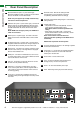
REAR PANEL DESCRIPTION
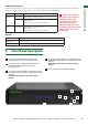
7. Rear Panel Description
1
Mirrored HDMI OUT ports 1~8 (From left to right) -
Mirrored to HDBaseT output, connects to the local HDMI
devices with HDMI or DVI to HDMI cables.
NOTE: this port supports up to 1080p resolution only.
A 4K source cannot be duplicated
2
HDBaseT OUT ports 1~8 (From left to right) - Connects to
HDBT IN ports of compatible HDBaseT Receivers (such
as RX-70-4K) with single Cat5e/6 cable for transmission
of HDMI Audio/Video, IR, RS232, Ethernet and 100W
power.
NOTE: HDMI OUT has higher priority over HDBT OUT
if both are connected.
3
HDMI IN ports 1~8 (left to right) - Connects to the local
HDMI source devices with HDMI cables or DVI to HDMI
cables.
4
IR RX Receiver ports 1~8 (left to right) - Connects to the
supplied broadband IR receivers for IR signal reception to
control the IR devices remotely from the matrix side.
5
Ethernet port - Connects to an active IP network to share
network access with any of the eight Ethernet equipped
devices at the HDBaseT end.
6
RS485 port - Connects to a RS485 device, such as a PC
or control system device, with a RJ45 to RS485 converter
and a serial cable for matrix control.
7
LAN port - Connects to an active IP network for control
of matrix via LAN (Telnet & Web GUI).
8
RS232 port - Connect to a RS232 device, such as a
PC or control system device, with the supplied USB to
UART cable or a direct serial cable for matrix control or
rmware upgrading.
9
IR Ext. port - Connects to a supplied IR receiver (not
broadband cable) for IR signal reception to locally control
the matrix.
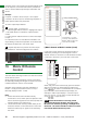
10
EDID DIP switch - Manual DIP setting for EDID
management for improved device connection
compatibility. (See EDID section for settings)
11
EDID DIP switch default setting diagram - Default factory
setting reference
13
Firmware Upgrade DIP switches - DIP settings to update
transmission card rmware.
14
IR TX ports 1~8 - Connects to the supplied IR emitters
for IR signal transmission to control the IR devices
remotely from the sink side.
15
Power switch - Powers matrix on/o
16
Fuse - To prevent voltage/current excess that can
damage circuitry. Lift cover to replace fuse
17
Power - AC 100~240V 50/60Hz power input.
18
GND - Electrical grounding to prevent static build up
12
Update mode switch
• Left position for Normal mode (default) – Normal
matrix function including RS232 control.
Note: Matrix software cannot be updated in this
setting.
• Right position for Update mode – normal matrix
function without RS232 control functionality. RS232
required for rmware update.
Note: Ensure switch is returned to the left
‘Normal’ mode after updating for full RS232 control
functionality.
RS232 cable required for rmware update.
2
3
5 6 7 8
9 10 11
12 13 14
15
16
17
18
4
1