
Instruction manual


7Technical Support: support@wyrestorm.com US: +1 866 677 0053 EU: +44 (0) 1793 230 343
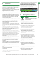
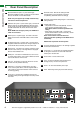
8. Connection & Operation
CONNECTION & OPERATION
The matrix allows any eight input channels (HDMI) to be
routed to any eight output channels (HDBaseT or HDMI),
regardless of source HDCP status, with HDMI OUT (up
to 1080p) a higher output priority over HDBT OUT (up to
4Kx2K) if both are connected.
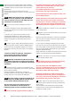
NOTES BEFORE INSTALLATION:
• Please be mindful of cable type and distance limitations
stated in Specification (Section 5 of this manual) 4K:
70m/230ft 1080p: 100m/328ft
• PoH functionality of the matrix is designed for powering
compatible HDBaseT RX-70-4K receiver units only. Non-
PoH receivers will require their own local power supply.
Non-WyreStorm display receivers may not be compatible
with this matrix product
• Use of straight-through Ethernet cables wired to
T568B standards is advised to achieve best results as
recommended by HDBaseT
• Connect/disconnect all cables gently during installation
and ensure power supplies are disconnected from all
devices before installation
• Ensure that any 4K sources and 4K display devices
used are compatible and outputting the correct
resolutions for EDID to be successfully negotiated and
signals received.
NOTE Both 4K and 1080p HD sources and displays
may be contained within the same distribution–
to combine 4K and HD sources and displays a
WyreStorm EXP-SCL-DAC-4K to HD/HD to 4K
scaler must be used between connected HDMI
display device
Visit wyrestorm.com for more information on 4K/HD
scaling and Dolby downmixing.
CONNECTION:
Connect source devices (such as: Blu-ray, computer,
games console, satellite/cable, music streaming device,
CCTV etc.) to the relevant input ports of the matrix output
modules 1-8.
Do Not Hotswap HDMI plugs or HDBaseT
connectors – Insert/extract cables carefully with
devices and mains SWITCHED OFF to avoid power
passed over the cable damaging circuitry.
For IR control of sources from a display zone,
connect an IR transmitter from the matrix to each source,
ensuring the IR emitter is attached directly over the
infrared receiving area of the device, using the adhesive
backing to secure in place.
HINT Locate the infrared sensor on devices by shining a
flashlight onto the display panel of sources and look for a
small sensor.
1
2
!
RX-70-4K
4K Source Device
Display 1 Mirror
Duplicate HDMI
IR receiver and IR emitter placed discretely on the
display with a clear line of sight to the remote handset
being used
IR emitter placed securely over
input device infrared sensor window
Power
LAN / Serial based
Control System
CAB-IR-LINK Cable
connecting from Control
System to IR RX port of
matrix
4K: 70m/230ft 1080p: 100m/328ft
Display 1
Control
System
Wi Router
1
1
2
5
5
3
7
2
6
4
8
8
Technical Support: support@wyrestorm.com US: +866 677 0053 EU: +44 (0) 1793 230 343
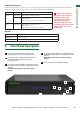
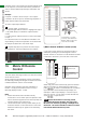
Connection
9. Connection
5V mains or
USB power
adapter
07
RS232 to
display
(optional)
Display 1 Mirror
Duplicate HDMI
Display 1
HDMI Source
IR TX emitter placed securely
over input device infrared
sensor window
IR RX jack plugged into
IR RX port of matrix with
receiver placed in clear
sight of remote control
Cat 5e/6/7 (up to 70m 230ft)
01
02
03
04
05
06
KEY
IRTX Emitter
IRRX Receiver
HDMI
UTP Cat5e/6/7
Control System
(Additional
control via
RS232)
LANRS485
08
IR RX receiver and IR TX emitter
placed discretely on the display with a
clear line of sight to the remote
handset being used
optional
Power
01
Connect each HDMI input source (such as: HD-DVD, PS3/,
XBOX360, satellite/cable, Blu-Ray etc.) to the HDMI inputs
of the MATRIX.
ATTENTION
Do Not Hotswap Plugs! Please insert and
extract cables carefully with the power SWITCHED OFF.
Connecting and disconnecting while the unit is powered
can result in damage to circuitry.
02
Attach the IR TX emitters directly over the infrared receiving
sensor of each input source using the adhesive backing.
You may need to adjust the position of the emitter after
installation to achieve the best results. Sometimes moving the
sensor to different areas of the source facia can improve IR
performance.
Plug the 3.5mm jack of the IR TX emitter into the
corresponding number IR TX port on the rear panel of the
MATRIX.
03
For two-way IR controlling the display from the matrix
side: Plug the 3.5mm jack of the IR RX receiver into the
corresponding IR RX port on the rear panel of the MATRIX,
ensuring the receiver is placed in clear view to receive an IR
signal.
NOTE
Make sure the IR jacks are in the same number
ports.
HINT
Locate the infrared sensor on devices by shining a
flashlight onto the display panel of sources and look for a
small sensor.
04
Connect a good quality, well terminated Cat 5e/6/7 cable
with an RJ45 connector wired to 568B standard at both
ends from the HDBT Output port of the MATRIX to the UTP
IN of the RX-1UTP-IR-70 DISPLAY RECEIVER (or, if using
another Wyrestorm extender set, connect the transmitter to
the matrix via the HDMI OUT port)
Ensure both RJ45 connectors are pushed securely into
each port and supported by the connector strain relief clip to
prevent them from becoming loose. The quality of termination
for your RJ45 is essential. Poor quality terminations lead to
intermittent performance and longer install times.
HINT
Although all Wyrestorm products are tested using
Cat5e as standard, we suggest using Cat6 as the preferred
cable due to its improved distribution capabilities.
If using a Duplicate display mirrored to the HDBT Output,
connect the display via the HDMI OUT port.
ATTENTION
We strongly recommend using the
supplied mounting brackets to secure the MATRIX
and the accompanying TRANSMITTER & DISPLAY
RECEIVER baluns. Any sudden movement of these
IR Emitter
IR Receiver
HDMI
UTP Cat5e/6
Ethernet
8
Technical Support: support@wyrestorm.com US: +866 677 0053 EU: +44 (0) 1793 230 343
Connection
9. Connection
5V mains or
USB power
adapter
07
RS232 to
display
(optional)
Display 1 Mirror
Duplicate HDMI
Display 1
HDMI Source
IR TX emitter placed securely
over input device infrared
sensor window
IR RX jack plugged into
IR RX port of matrix with
receiver placed in clear
sight of remote control
Cat 5e/6/7 (up to 70m 230ft)
01
02
03
04
05
06
KEY
IRTX Emitter
IRRX Receiver
HDMI
UTP Cat5e/6/7
Control System
(Additional
control via
RS232)
LANRS485
08
IR RX receiver and IR TX emitter
placed discretely on the display with a
clear line of sight to the remote
handset being used
optional
Power
01
Connect each HDMI input source (such as: HD-DVD, PS3/,
XBOX360, satellite/cable, Blu-Ray etc.) to the HDMI inputs
of the MATRIX.
ATTENTION
Do Not Hotswap Plugs! Please insert and
extract cables carefully with the power SWITCHED OFF.
Connecting and disconnecting while the unit is powered
can result in damage to circuitry.
02
Attach the IR TX emitters directly over the infrared receiving
sensor of each input source using the adhesive backing.
You may need to adjust the position of the emitter after
installation to achieve the best results. Sometimes moving the
sensor to different areas of the source facia can improve IR
performance.
Plug the 3.5mm jack of the IR TX emitter into the
corresponding number IR TX port on the rear panel of the
MATRIX.
03
For two-way IR controlling the display from the matrix
side: Plug the 3.5mm jack of the IR RX receiver into the
corresponding IR RX port on the rear panel of the MATRIX,
ensuring the receiver is placed in clear view to receive an IR
signal.
NOTE
Make sure the IR jacks are in the same number
ports.
HINT
Locate the infrared sensor on devices by shining a
flashlight onto the display panel of sources and look for a
small sensor.
04
Connect a good quality, well terminated Cat 5e/6/7 cable
with an RJ45 connector wired to 568B standard at both
ends from the HDBT Output port of the MATRIX to the UTP
IN of the RX-1UTP-IR-70 DISPLAY RECEIVER (or, if using
another Wyrestorm extender set, connect the transmitter to
the matrix via the HDMI OUT port)
Ensure both RJ45 connectors are pushed securely into
each port and supported by the connector strain relief clip to
prevent them from becoming loose. The quality of termination
for your RJ45 is essential. Poor quality terminations lead to
intermittent performance and longer install times.
HINT
Although all Wyrestorm products are tested using
Cat5e as standard, we suggest using Cat6 as the preferred
cable due to its improved distribution capabilities.
If using a Duplicate display mirrored to the HDBT Output,
connect the display via the HDMI OUT port.
ATTENTION
We strongly recommend using the
supplied mounting brackets to secure the MATRIX
and the accompanying TRANSMITTER & DISPLAY
RECEIVER baluns. Any sudden movement of these
RX RX
1
1
2
2
10
Technical Support: support@wyrestorm.com US: +866 677 0053 EU: +44 (0) 1793 230 343
BASIC REMOTE CONTROL
11. Basic Remote Control
OUTPUT
CHANNEL
INPUT SELECT
1
2
3
4
5
6
7
8
To change handset battery
Pinch here and pull out
Install battery ‘+’ side
up and only use CR
2025 3V batteries. Slide
compartment back into
the handset.
The same basic switching functions can also be accessed via the
remote control.
Operation of the handset is the same regardless of location –
locally (source/IR emitter) or remotely (display/IR receiver).
Simply toggle through the INPUT sources connected to the
matrix by pressing the left/right arrow buttons in each numbered
OUTPUT section on the handset.
previous / next buttons
When using the remote control locally, i.e. pointed directly at the
matrix, the previous / next buttons are used to scroll between the
input sources connected to the matrix for each individual output
display. So for example, using the previous / next buttons for 1
allows you to select the source to be set to display 1 manu-ally.
See below:
Matrix System Code Switch
The MX0606/0808-PP features an intuitive IR ‘Call Back’ system
of control through which the matrix is able to distinguish where the
remote handset is being used to change INPUTS and OUTPUTS
and is able to switch accordingly depending on the user’s location.
As such, the function of the handset buttons and operation differs
depending on where the handset is being used.
In the event that two MX0606/0808-PP units are used side
by side in the rack, the matrix is capable of switching between
two distinct IR System Codes to allow control of either matrix
individually via the hand-set.
OUTPUT
CHANNEL
INPUT SELECT
1
2
3
4
5
6
7
8
OUTPUT
CHANNEL
INPUT SELECT
1
2
3
4
5
6
7
8
OUTPUT
CHANNEL
INPUT SELECT
1
2
3
4
5
6
7
8
System Code Switch
The default system setting is 0x00 to control one matrix, but
pressing the SYSTEM CODE button on the handset THREE
TIMES rapidly activates the alternative Matrix SYSTEM CODE
0x4e, allowing independent control of a second unit. Pressing the
button three times again to reverts back to default 0x00 setting.
NOTE
Changing the System Code is only necessary if you
are using two identical units within close range of the IR
signal. If using in different parts of the same room it is likely
that you will not need to change the setting.
HINT
If your remote control is not working, before changing the
battery, try changing the System Code on the handset in case it
has accidentally been switched to an alternative matrix control
mode.
Remote Control at the Display End (Remote IR)
When controlling the matrix remotely from the display side, the
matrix automatically detects which particular output location
the user is at and only allows the selection of sources 1-8 for
that particular location using the button - the right hand
button will be deactivated.
For example, if you are in the Master Bedroom with a display
connected to output 3 of the matrix, the output zone is
automatically detected so options 1-8 will correspond to sources
1-8 on the matrix. Press buttons 1-8 to scroll through your
options as you would channels on a regular TV remote.
OUTPUT
CHANNEL
INPUT SELECT
1
2
3
4
5
6
7
8
OUTPUT
CHANNEL
INPUT SELECT
1
2
3
4
5
6
7
8
OUTPUT
CHANNEL
INPUT SELECT
1
2
3
4
5
6
7
8
Optional
EXP-SCL-DAC-4K
4K/HD Scaler
Optional
EXP-SCL-DAC-4K
4K/HD Scaler