
Instruction manual


9
Technical Support: support@wyrestorm.com US: +1 866 677 0053 EU: +44 (0) 1793 230 343
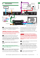
IR Call-back of Matrix and Source Devices
HDMI Source
Output Display 1
HDMI Cable
IR Receiver
IR Receiver
Cat5e/6/7 up to
40m (131ft)
HDMI Input 1
IR TX 1
HDMI Input 2
IR TX 2
HDMI Input 3
IR TX 3
HDMI Input 4
IR TX 4
P
/
N
:
R
X-Q
I
-
I
R-
4
0
1 2 3 4
1
1 2 3 4
2
1 2 3 4
3
1 2 3 4
4
IR Path IR PathIR Path
UTP Out 1
UTP Out 2
UTP Out 3
UTP Out 4
1 2 3 4
1
1 2 3 4
2
1 2 3 4
3
1 2 3 4
4
The MX0404-QI is not only a switcher and extender of
multiple HDMI signals to multiple HDMI receivers located
remotely, it also passes IR control signals through the IR
call-back system to the matrix and HDMI sources for full,
independent control of all connected inputs from output
locations using your remote handset.
This is accomplished by placing a series of IR Emitters on
source devices you wish to control and IR Receivers at all
output locations you wish to control from to enable the IR
control signal to be delivered via single Cat5e/6/7 cable
connecting the two.
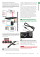
At Matrix end: Insert the 3.5mm jacks of the IR TX
Emitters included with the unit into the IR TX Emitter ports
at the rear of the matrix according to input. The IR signal
is added to the HDMI of the input device so, for example,
if the user is watching Blu-ray on input 3, the IR signal
will be directed through the IR TX3 socket to control the
device.
As each IR TX port is allocated to an individual HDMI
input port, if the user is unable to establish IR control of
the device, care should be taken to check that, firstly,
the IR emitter and HDMI input ports match (Input 1-TX1,
Input2-TX2 etc.) with plugs secured in correct ports,
and secondly, that the IR TX emitter sensors are firmly
attached directly to the front of inputs and covering
infrared sensor windows of the source devices.
Some later adjustment may be needed to the location
of the sensor to achieve the best performance results -
sometimes moving the sensor to different areas on the
source can improve IR performance.
HINT Infrared receiving areas of devices can be
located by shining a flashlight onto the front of
the device – the sensor should be able to be seen
through the plastic as a small, round object inside.
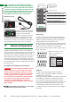
At display end: Insert the IR RX Receiver jack into
the IR RX port of the RX-1UTP-IR-40 receiver baluns,
with the IR receivers themselves placed in clear view on
or near the displays to receive an infrared signal from the
remote handset used to control inputs.
Fasten firmly to the surface to avoid displacement.
Attention Misplaced or poorly secured IR Emitters
and Receivers may result in intermittent IR control
signals passed to and from the matrix. Check your
placement and adjust if necessary.
P/N: RX-QI-IR -40
HDMI OUTDIS TANCE
EQ
MAX
MIN
RX-1UTP-IR-40
1
2
BASIC OPERATION