
Certificate Of Compliance


HBCS Report # FCC_12003 Page 9 of 17
2. Radiated Emissions
Test
Requirement(s):
§15.109 Test Engineer(s): Frank Farrone
Test Results: Pass Test Date(s): 02/23/12
Test Procedures:
The final radiated emissions test was performed using the parameters described above as worst case. That
final test was conducted at a facility that meets the ANSI C63.4 NSA requirements. The frequency range
noted in the data sheets was scanned/tested at that facility. Emissions were maximized as specified, by
varying table azimuth, antenna height, and manipulating cables.
Using the mode of operation and configuration noted within this report, a final radiated emissions test was
performed. The frequency range investigated (scanned), is also noted in this report. Radiated emissions
measurements were made at the EUT azimuth and antenna height such that the maximum radiated
emissions level will be detected. This requires the use of a turntable and an antenna positioner. The
preferred method of a continuous azimuth search is utilized for frequency scans of the EUT field strength
with both polarities of the measuring antenna. A calibrated, linearly polarized antenna was positioned at
the specified distance from the periphery of the EUT.
Note: The specified distance is the horizontal separation between the closest periphery of the
EUT and the center of the axis of the elements of the receiving antenna. However, if the receiving
antenna is a log-periodic array, the specified distance shall be the distance between the closest
periphery of the EUT and the front-to-back center of the array of elements.
Tests were made with the antenna positioned in both the horizontal and vertical polarization planes. The
measurement was varied in height above the conducting ground plane to obtain the maximum signal
strength. Though specified in the report, the measurement distance shall be 3 meters. At any
measurement distance, the antenna height was varied from 1 meter to 4 meters. These height scans apply
for both horizontal and vertical polarization, except that for vertical polarization the minimum height of
the center of the antenna shall be increased so that the lowest point of the bottom of the antenna clears the
ground surface by at least 25 cm.
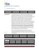
Frequency Range (MHz) Peak Data (kHz) Quasi-Peak Data (kHz) Average Data (kHz)
30 MHz to 1 GHz 120 kHz 120 kHz N/A
1 GHz to 11 GHz 1MHz N/A 1MHz
Measurements were made using the bandwidths and detectors specified. The video filter was at least as wide as the IF
bandwidth of the measuring receiver.
Table 3. Radiated Emissions – Measurement Bandwidth