
User's Manual


400 B/W Reflection Densitometer
6-106-10
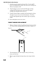
Figure 5-6
3. Carefully remove old Lamp assembly [3] by lifting upward and
discarding.
Lamp Installation
1. Align the flat edges of Optics PCB [2] and new Lamp PCB [3],
and insert into Optics assembly. (figure 5-6)
NOTE: EXTREME CAUTION MUST BE TAKEN WHEN
INSTALLING NEW LAMP. DO NOT BEND LAMP LEADS.
2. Insert and tighten the two lamp screws [4].
3. Carefully reinstall Optics assembly into densitometer by facing
flat edge of sensor nose to front of densitometer. Work into
position until alignment pins and connector pins are properly
seated.
4. Insert and tighten sensor nose screws [1]. (Figure 5-5)
4
3
2