Indoor/Outdoor Color Camera with Built-in 2.4 GHz Wireless Video Sender, plus X10 controlled power supply, and separate Video Receiver.
INTRODUCTION Your Wireless Camera Kit consists of a Color Video Camera with built-in 2.4 GHz Video Sender, and a Video Receiver unit which you connect to a TV anywhere in your home (up to 100 ft. away from the Camera). The Camera/Video Sender converts the video and audio signals from the camera into a radio signals and transmits them (even through walls) to the Video Receiver.
11. Power Sources - This product should be operated only from the type of power source indicated on the marking label. If you are not sure of the type or power supply to your home, consult your product dealer or local power company. For c) If the product has been exposed to rain or water, d) If the product does not operate normally by following the operating instructions.
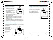
CONTENTS CONTROLS AND CONNECTIONS ........................................ 7 CAMERA/VIDEO SENDER, REMOTE CONTROLLED ....................... POWER SUPPLY, AND VIDEO RECEIVER ................................ 7 CAMERA/VIDEO SENDER .................................................. 8 VIDEO RECEIVER ............................................................. 9 CONTROLS AND CONNECTIONS CAMERA/VIDEO SENDER VIDEO R ECEIVER (BOTTOM VIEW) TV 2.4 GHz Video Antenna Channel Switch CONNECTING UP ............
CONTROLS AND CONNECTIONS CAMERA/VIDEO SENDER VIDEO RECEIVER 2.4 GHz Video Antenna 2.4 GHz Video Antenna TV Output Connector Mounting plate ON-OFF TO TV Switch VIDEO OUT AUDIO OUT Set channel switch to match setting on Video Receiver. Power Supply Jack TV Channel Switch 2.4 GHz Channel Switch A/V Jacks (on bottom) Cable adapter.
CONNECTING UP SETTING UP THE CAMERA /VIDEO SENDER, CONTROLLED POWER SUPPLY AND REMOTE Referring to the diagrams below and on the next page: 2.4 GHz Video Antenna Set channel switch to match setting on Video Receiver. 1. Attach the camera to a wall using the screws provided. 2. If you install the camera outdoors, make a small hole in your exterior wall and pass the low voltage power jack through it. 3. Plug the XM10A's power supply jack into the socket on the adapter cable from the camera. 4.
HOOKING UP THE VIDEO RECEIVER IF YOUR TV IS A/V DEVICE 1. Connect a set of Audio/Video cables to the A/V OUT jacks on the Video Receiver. Connect the other end to your TV (use either L or R channel for audio). VIDE O A UDIO TO TV TV 2. Plug the Video Receiver's Power Supply jack (the power supply with NO code wheels) into the Video Receiver and plug the power supply into a 120 volt wall outlet.
FINE TUNING YOUR SYSTEM The Wireless Video Sender usually works best with the flat faces of the antennas on the Sender and Receiver unit facing each other (i.e. in “Line of sight” - see diagram below). Sometimes, however, reflections and other effects in the home may affect the signal so that some adjustment of either the Sender or Receiver antenna may be necessary to get the best the signal. WARRANTY 12 MONTH LIMITED WARRANTY X10 WIRELESS TECHNOLOGY, INC.
X10.com, a Division of X10 Wireless Technology, Inc. 3824 North 5th St., Suite C, North Las Vegas, NV 89030 Web Site: www.x10.