Indoor Wireless/Wired IP Network Camera Model XX34A User Manual
CONTENTS 1.1 FEATURES ............................................................................................................................................................................................. 3 1.2 PACKING LIST ....................................................................................................................................................................................... 3 1.3 PRODUCT VIEWS .............................................................................
1 INTRODUCTION This is an integrated wireless IP Camera solution. It combines a high quality digital Video Camera with network connectivity and a powerful web server to bring clear pictures to your Desktop from anywhere on your local network or over the Internet. The main function of the camera is to transmit remote video over IP network. The high quality video image can be transmitted with 30fps speed on the LAN/WAN by using MJPEG hardware compression technology.
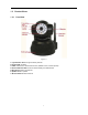
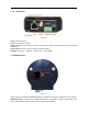
1.3 1.3.1 Product Views Front View Figure 1.1 1 Light Sensitive Hole: For light sensitive photocell 2 Infrared LED: 10 LEDs 3 LENS: CMOS sensor with fixed focus lens. (Default is 6mm, 3.
1.3.2 Rear Panel Figure 1.2 LAN: RJ-45/10-100 base T Power: DC 5V/2A power supply Network Light: The green LED is on when connected to the network, the yellow LED blinks when data is transferred. Audio Output: The jack is used to connect an external speaker I/O PINS: 1: Output A 2: Output B 3: Alarm input 4: Input (GND) 1.3.3 Bottom View Figure 1.3 Please note the unique MAC and DDNS addresses on the bottom of the camera (different for every camera).
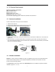
1.4 PC System Requirements System configuration requirements: CPU: 2.06 GHZ or above. Memory: 256M or above. Network Card: 10M or above. Display Card: 64M or above memory. Recommended Operating system: Windows XP, Windows Vista, Windows 7. 1.5 Hardware Installation Follow the steps below to set up your camera hardware. 1. Install the Wi-Fi antenna. 2. Plug the power adaptor into the camera and into an AC outlet. 3. Plug the network cable into the camera and router/switch. 4.
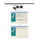
2. ActiveX: Double click “Appinstall.exe”—“Next”—“Install”—“Finish”. Figure 1.5 Figure 1.6 Figure 1.
Figure 1.8 After this is done, the icon “IP Camera Tool” will be displayed on your desktop. CAUTION: Before installing and using the product, please read the following precautions carefully and make sure they are fully understood. Use only the power adaptor included with the product. Use of an unauthorized power adapter may cause damage to your IP Camera. The IP Camera should be installed indoors only. Do not touch the lens of the IP Camera. The optimum focus range has been set for you.
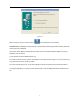
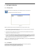
2. SOFTWARE OPERATION 2.1 IP Camera Tool When the Device has been mounted properly, you can double-click the Icon “IP Camera Tool” and a dialog box shown in Figure 1.9 will pop up. Figure 1.9 Note: The software searches IP Servers automatically over your LAN. There are 3 cases: 1. No IP Cameras found within LAN. After about 1 minute search, the Result Field will show “not found IP Server” and the program shut down automatically. 2. IP Cameras have been installed within LAN.
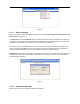
Figure 2.0 2.1.1 .1 Basic Properties There is some device information in the Basic Properties, such as Device ID, System Firmware Version, and Web UI Version.(Figure 2.1). The Device ID is the camera’s MAC ID, which should be the same as shown on the sticker on the bottom of the camera. Every camera has a unique MAC ID. So if there are many IP addresses shown in the list, check the MAC ID on the bottom of the camera, so you can ensure which camera it is.
Figure 2.2 Obtain IP from DHCP server: If clicked, the device will obtain IP from DHCP server. In other words, the camera will have a dynamic IP. (Make sure the Router which the camera connects to has DHCP function and DHCP is enabled). (Figure 2.2). Figure 2.3 IP address: Fill in the IP address assigned and make sure it is in the same subnet as the Gateway, and the subnet should be the same as your computer or router. (I.e. the first three sections are the same).
2.1.1.3 Upgrade Firmware Enter the correct User and Password to upgrade system Firmware and Web UI. Please upgrade system firmware first and then upgrade Web UI or it may damage the camera.(Figure 2.4). Figure 2.4 Please download the firmware package for the correct type of your camera before you upgrade. Follow the upgrade document carefully to upgrade. Please see readme file first before you upgrade. CAUTION: You should not upgrade the firmware unnecessarily.
2. To access the camera by IE Browser directly, just type the camera’s IP address, for example, if the camera’s IP address is 192.168.1.123: Figure 2.5 Figure 2.6 The default user name is admin, no password (leave blank). Input the correct user name and password, the Sign In interface will pop-up. There are three models to login (figure 2.7). Figure 2.7 (1) Active Mode (For IE Browser): available in IE 6.0 or above. (2) “Server Push Mode”: available in Firefox, Safari, and Google Chrome browser.
2.3 For IE Browser Choose ActiveX Mode (For IE Browser), and sign in. Figure 2.8 Figure 2.9 The first time you login to the camera, you might get an ActiveX prompt as in the picture above, please click the prompt and choose Run Add-on, refresh and login to the camera again, then will see live video, as below. Figure 3.
Note: If there is still no live video after you run ActiveX, and a red cross shows in the center of the screen, or even just a black screen, please try to enable the ActiveX options of IE security settings. Please do the following steps: 1. Close the firewall of your computer. 2.
Figure 3.2 NOTE: Make sure that your firewall or anti-virus software doesn’t block the software or ActiveX. If you couldn’t see live video, please close your firewall or anti-virus software, and try again. 2.4 For Safari, Firefox, Google Browser Choose Server Push Mode (For Safari, Firefox, Google Browser), and sign in. Server Push Mode doesn’t support ActiveX, so some functions are not available, such as Play, Stop, Record, Audio, Talk etc. If you want to use these functions, please use IE browser.
2.5 For Mobile Phone Choose Sign in mobile phone, and sign in. Mobile phone doesn’t support ActiveX, so only some basic functions are available in this mode. It supports iPhone, Smart phone, 3G phone, etc. Normally, if the mobile phone supports network video, then it should work with your IP Camera. Figure 3.4 2.
Figure 3.5 Channels: The IE software supports 9 channels. Click to get different windows. Click this one to view the main channel of the camera you login to. Click this one to view 4 Channels of cameras that are connected, from CH1 to CH4. Click this one to view 9 Channels of cameras that are connected, from CH1 to CH9. NOTE: If you want to view 4/9 channels, you should set the Multi-Device first (See 3.1 Multi-Device Settings).
OSD Settings: Figure 3.6 OSD: Means “On-Screen Display”, click “Audio video” > “OSD”, set display date and time on the video. Disabled: Clicking this one means clear the OSD. Color: Can set the OSD text color as black, yellow, red, white, blue etc. Add time stamp on record: if you click this, there will be time OSD on record video files. Figure 3.7 Rate and Resolution: Rate: Set video frame here, from “full-speed to 1fp/5s”. (Figure 3.8).
Figure 3.8 Figure 3.9 TOP Menu: Figure 4.0 Click to get live video. When you want to get back to live video from other menus, just click it. Only under live video, you can do the operation on the right side, such as play, stop, snapshot etc. Click to get into play mode, when you click the stop icon, the video will be stopped, then if you click the play icon, it will show the video again. Click to stop the live video. You can click the play icon if you want to see live video again. Click to get snapshot.
2.8 For Operator When you login as Operator, you can enter the IP Camera for Operator. For operator, it not only supports all the functions for Visitor, but also supports these functions below: Figure 4.1 Audio Video Settings Figure 4.2 Audio buffer: Click this icon, it will show five numbers, which means 1/2/3/4/5 seconds buffer of audio. Reversal: Click this icon to reverse (flip) the image. Click again to go back to normal. Mirror: Click this icon to see a mirror image.
Mode, Bright, Contrast Settings Figure 4.3 Mode: This mode is optional, 50HZ/60HZ for the users who use 50HZ/60HZ frequency, outdoor for users who want to use the camera to monitor towards an outdoor environment. NOTE: The camera should be used in an indoor environment (unless protected from the elements). Bright: Set the parameters to adjust the image quality of the video. Click to adjust the value. Contrast: Set the parameters to adjust the image quality of the video. Click to adjust the value.
Preset Settings Figure 4.5 Set Preset Position. It supports 15 preset positions. To control the camera’s rotation to a preset position, click Set Preset Position button it will pop-up a dialog frame (Figure 4.5), choose the number (1-15) you want to set it to. NOTE: if you set different positions with the same number, the camera will record the last position setting only. Call Preset Position. It supports 15 preset positions.
3 SETTINGS AS ADMINISTRATOR Administrator supports all the settings and operations of the camera. There are some special functions only for administrator as below: Figure 4.6 3.1 Multi-Device Settings Multi-Device Settings This camera can support max. 9 device channels at the same time. 3.1.1 Set Multi-Device in LAN In the Multi-Device Settings page, you can see all devices searched in LAN. The 1st device is the default one. You can add more cameras listed in LAN for monitoring.
Figure 4.7 Click Live Video and then select to see four channels, or click Figure 4.8 25 to see nine channels.
Figure 4.9 3.1.2 Set Multi-Device for WAN If you want to view cameras from the internet, you have to add these devices by DDNS domain name. Make sure all these cameras you want to add have DDNS set successfully. (See 3.7 DDNS Service Settings) Login to the first camera by DDNS domain name and port, this camera will be as the host camera. Figure 5.0 Click Multi-Device, select Multi-Device Settings. Choose the 2nd Device; fill in the 2nd camera’s Alias, Host, Http Port, User, Password, click Add.
name, and without “http://”, it’s not the LAN IP address. If you have several cameras, you can use the same DDNS domain name, just set different port number for each different camera. Figure 5.1 Note: Add the other camera in the same way, Click submit to add all of them. Figure 5.
Click Live Video and then select to see four channels, or to see nine channels. In this case, you can see all the cameras from a remote position by internet, for example, if you are on a business trip, you can use the first camera’s (Host camera) DDNS to view all the devices via the internet. Figure 5.3 3.1.3 Upgrade Device Firmware If you want to upgrade the camera, please upgrade Device Firmware first, then upgrade Web UI. Click Browse and choose correct bin file, then click Submit to do upgrading.
3.1.4 Restore Factory Settings Click Restore Factory Settings, will pop-up a prompt, select OK, all the parameter will be returned to factory settings, and the device will reboot. Figure 5.5 3.1.5 Reboot Device Click Reboot the device, will pop-up a prompt, select OK, then the device will reboot Figure 5.6 3.2 Network Settings Click Network, will pop-up the prompt as below: 3.3 Basic Network Settings Here you can set the camera’s IP address; i.e.
Figure 5.7 If you don’t know the Subnet Mask, Gateway, DNS Server. Please check the Local Area Connection Status of your computer; it contains all this information, steps as below: 1. Control PanelNetwork ConnectionsLocal Area Connections Support Details 2. Find the local connection icon from taskbar, left click it, choose Support Details Figure 5.8 Figure 5.
If you don’t know the DNS Server, you can set it the same as Gateway. If the router supports DHCP function, you can choose “Obtain IP from DHCP Server” to get dynamic IP. Figure 6.0 Http Port: In most cases, you can leave this value as-is. However, if your Internet Service Provider blocks this port, you may change it to another port number such as 85. 3.4 Wireless LAN Settings Figure 6.1 You should set up your camera using a wired connection before you attempt to use it wirelessly.
Figure 6.2 Figure 6.3 Figure 6.
Figure 6.5 3.5 ADSL Settings When connected to the Internet through ADSL directly, you can enter the ADSL username And password obtained from ISP. Figure 6.6 3.6 Figure 6.7 UPnP Settings Click UPnP Settings to choose Using UPnP to Map Port: Figure 6.8 Select it and click Submit, then the camera will support UPnP port forwarding automatically. It’s helpful for using DDNS. If your router supports UPnP, then you won’t need do port forwarding in the router.
Figure 6.9 NOTE: Here UPnP is only for port forwarding. It relates to the security settings of your router, make sure the UPnP function of your router is ON. Attention: If your router doesn’t support UPnP function, it may show error information. So we recommend you do port forwarding manually in your router. (For details see Figures 7.4 - 7.9). 3.7 DDNS Service Settings Figure 7.0 There are 2 options: Manufacturer’s DDNS: This domain is provided by the manufacturer.
Third Party DDNS If you use third party DDNS, please choose the server you use, such as “3322.org” or “dyndns.org” as below: Figure 7.2 Figure 7.3 You have to register an account first, enter the user, password, and host. NOTE: Only one DDNS can be chosen, for example, if you use the manufacturer’s DDNS, the third party one won’t work, if you use the third party DDNS, the manufacturer’s one won’t work. To change the camera’s port.
Figure 7.4 Make sure the “Subnet Mask”, “Gateway”, “DNS Server” is the same as your router. Set Port Forwarding in the router. This is the most important step. You need to set port forwarding in your router, to refer to the IP of your camera correctly, for DDNS to work. There are so many kinds of routers, so it’s difficult to show fixed steps, but here are some samples of different router’s port forwarding settings, just for reference: TP-LINK: 1. Login to the router. 2.
BELKIN: 1. Login to the router. 2. Choose “Firewall”, select “Virtual Servers” 3. Input the port (don’t use 80) and IP address, then click save. NOTE: The port and IP address should be the same as the camera. Figure 7.6 DLINK: 1. Login to the router. 2. Choose “Advanced”, select “Virtual Servers” 3. Input the port, IP address, Protocol, then click save. NOTE: The “public port” & “private port” should be the same as camera’s port, choose the protocol to be “both”. Figure 7.
After all these 4 steps are done, you can use DDNS, check the DDNS status from the camera as below, and get the link of DDNS for internet viewing. Step: “Login”>”System”>”Device Info” Figure 7.8 Figure 7.9 3.8 System Settings Figure 8.
3.8.1 Device Info You can find the information about Device ID, Firmware Version, Embedded Web UI Version, Alias, Alarm Status, DDNS Status, UPnP Status and MSN status. Figure 8.1 3.9 Alias Settings Default device name is anonymous. You set any new name for your camera here, then click Submit. Figure 8.2 3.10 Date &Time Settings Set the date and time for your camera. Choose the Clock Time zone of your country. You can choose Sync with NTP Server (Figure 8.3) or Sync with PC Time (Figure 8.4).
Figure 8.4 3.11 Users Settings Eight accounts are acceptable for this system. Here you can set the user names and password as Administrator, Operator or Visitor, with permission for them as below: Visitor: In this mode, you can only view. (Details 2.7). Operator: You can control the direction of IP Camera and set some parameters. (Details 2.8). Administrator: You can setup the advanced configurations of the IP Camera. (Details 3.1-3.22). Figure 8.
3.12 Pan, Tilt, (PTZ) Settings (note, there is no Zoom feature on this model) Figure 8.6 1. Go center on boot: The camera rotates to the center automatically when it starts. 2. PT speed: Set Pan/Tilt speed. 3. Upward patrol speed: Set the speed of cruising upward. 4. Downward patrol speed: Set the speed of cruising downward. 5. Leftward patrol speed: Set the speed of cruising leftward. 6. Rightward patrol speed: Set the speed of cruising rightward.
1)Backup: Backup all the IP Camera Parameters, if you want to save all the current settings that you have set already, you can click Submit, then all the parameters you set will be stored as a parameters bin file. 2)Restore: Restore all the IP Camera Parameters, if you want to change the camera’s settings to a certain status which has a backup, click Browse to load the bin file, then Submit it. Log Figure 8.9 Record User information, including weekday, date, time, user name, visitor IP address etc.
After you run your MSN, open the chat dialog, type in the word “url?”, after a few seconds, you will get a reply for the remote access IP address for this IP camera. 3.15 Other Settings Figure 9.0 Here you can configure some additional functions such as Motion Detection, Alarm, IO Linkage, Schedule, FTP Upload, Alarm Mail Alert, Record Path, etc. 3.16 Mail Service Settings Set Mail Service Settings to enable the camera to send e-mail alerts when motion is detected. Figure 9.
Sender: Make sure the sender mailbox server provider supports SMTP, and the mailbox should not enable SSL or TSL encryption. Receiver: Here you can set four receivers. For receiver, there is no SMTP limitation. SMTP Server: The sender’s SMTP Server. SMTP Port: The sender’s SMTP Port, usually is 25, some SMTP servers have their own port, such as 587. Need Authentication: If there is SMTP user & password, please select authentication. SMTP User: Input correct SMTP User here.
3.17 FTP Service Settings Set the FTP Service, you can upload images to your FTP server when motion is detected. Figure 9.3 Figure 9.4 FTP Server: If your FTP server is set up in LAN. You can set as Figure 9.3. If you have an FTP server that can be accessed from the Internet, you can set as Figure 9.4. FTP Port: Usually the port is 21. FTP Upload Folder: Make sure that the folder you plan to store images in exists. The camera cannot create the folder itself. Also, the folder must be erasable.
Figure 9.5 If it prompts error information as follows. 1) Cannot connect to the server. Please check FTP Server is correct. 2) Network Error. Please try later. 3) Server Error. 4) Incorrect user or password. Please check the username and password is correct. 5) Cannot access the folder. Please be sure the folder exists and your account is authorized. 6) Error in PASV mode. Please be sure the server supports PASV mode. 7) Error in PORT mode. PASV mode should be selected if the device is behind a NAT.
Figure 9.7 After you enable motion detect armed, if there is motion detected, the Alarm Status will turn to Motion Detect Alarm. (Figure 9.8). Figure 9.8 3.18.2 Motion Detect Sensitivity You can choose level 1-10; level 10 means the most sensitive, 1 means the least sensitive. Figure 9.
3.18.3 Alarm Input Armed / IO Linkage on Alarm If you want to connect external alarm devices, when it’s an alarm input device, choose Alarm Input Armed to enable it, when it’s an output device, choose IO Linkage on Alarm to enable it. Figure 10.0 There are two options for Trigger Level. (Figure 10.1). High: When the external alarm device is close, then the alarm is triggered. Low: When the external alarm device is switching off, then the alarm is triggered. Figure 10.
3.18.4 IO Pins for IO Alarm Linkage Figure 10.3 I/O PINS: 1 Output 2 Output 3 Alarm input 4 Input (GND) Input pins: The input pins can be used for 1-way external sensor input. For example, you may connect a Passive Infrared (PIR) Sensor to it for motion detection. When the external sensor is triggered, the IP camera can be programmed to send an e-mail with a picture or to control the internal relay output.
Figure 10.5 Sound on Alarm When motion is detected, there will be a beep sound during the alarm, you can control this sound here. If Enabled, there will be sound once alarmed. If Canceled, there will be no sound once alarmed. Record on Alarm If you want the camera do recording for every alarm, choose Record on Alarm to enable it. If you do not want the camera do recording once alarm triggered, cancel it here. Figure 10.6 Once an alarm has occurred, there will be indication as below: 1.
3.20 Path Settings Figure 10.8 Here you can set record path and alarm record path for the camera. Figure 10.9 Record Path: Here you can set the manually record path. Click then start manual recording, the record file will be saved to the specified path you set here. Alarm Record Path: Here you can set the alarm record path. When motion is detected, and record enabled, it will start alarm record automatically, the record file will be saved to the specified path you set here. Figure 11.
3.21 Server Push Mode (For Safari, FireFox, Google Browser) Choose Server Push Mode, login the camera, you will see the main user interface as below: Figure 11.2 NOTE: Server Push Mode does not support ActiveX. Play, Stop, Record, Audio, Talk, Multi-device settings, Path settings functions are controlled by ActiveX, so if you use Safari, Firefox, Google chrome browser, it is not possible to use these options. The other functions are the same as for IE Browser.
3.22 Sign in mobile phone If you are using a mobile phone, choose Sign in mobile phone, login to the camera, you will see the main user interface as below: Figure 11.3 NOTE: Mobile phone Mode doesn’t support ActiveX. In mobile phone mode, it only supports some simple functions, such as Resolution, Mode, Bright, Contrast, Pan/Tilt control, Snapshot, Reversal, Mirror, IO Linkage functions.
4. APPENDIX 4.1 Frequently Asked Questions Note: For most problems you might encounter, please check Network connections first. Check the working status revealed by the indicators on the network server, hub, exchange and network card. If abnormal, check the network connections. 4.1.1 I have forgotten the administrator username and/or password. To reset the administrator username and password, press and hold down the RESET BUTTON for 15 seconds.
4.1.6 UPnP always fails UPnP only contains port forwarding in our recent software. Sometimes, it might fail to do port forwarding automatically because of firewall or anti-virus software. It also relates to your router’s security settings. So we recommend you do port forwarding manually. You can view your camera via the Internet successfully after you do port forwarding manually in your router. 4.1.
4.1.13 There’s no picture (Problems with ActiveX Controller) If using IE browser to connect the camera for the first time, and there is no image displayed, you might need to install ActiveX. You need to change some browser settings to enable ActiveX. (See: For IE Browser). 4.1.14 Problems with network bandwidth The image frame rate is subject to the following factors: 1. Network bandwidth. 2. PC performance, network environment and display preference setting (brightness, theme, etc). 3.
5. SPECIFICATIONS Model XX34A Image Sensor Sensor 1/4” Color CMOS Sensor Resolution 640 x 480 Pixels (300k Pixels) IR Lens f: 6mm, F 2.0 (3.6mm lens optional) Viewing Angle 60 Degree (3.6mm lens is 90Degree) Minimum Illumination 0.5Lux @ F2.
6. OBTAINING TECHNICAL SUPPORT We hope your experience with your IP network camera is enjoyable, but if you experience any issues or have any questions that this User’s Guide has not answered, please visit www.x10.com/support, e-mail support@x10.com or call 1-800-442-5065. This user manual is based on the latest version of our camera. System Firmware: 17.37.2.41 Web UI: 20.8.1.