
User's Manual
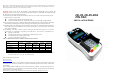

1. CONNECTING THE FD35 PIN PAD
The FD-35, FD-35-ZKA device can be used to connect with PC/
terminal. It supports RJ12 offset, USB interfaces via different
cable types such as RJ12 offset and standard USB via mini din
(Figure 1) type connector.
Note: Turn off or unplug the terminal/PC whenever you
connect or disconnect the PIN Pad. Be sure the terminal/PC
is not processing data when powering down.
Plug the USB connector of FD-35, FD-35-ZKA to the USB port
at the top end of a PC.
PIN pad Input voltage: 5Vdc / 500mA (USB)
Operating Temperature: 0ºC ~ 40 ºC
RTC battery: 3V, CR2032
Caution: Risk of explosion if the battery is replaced by an
incorrect type. Please dispose of used battery according to the
instructions.
Caution:
• It shall not be removable from other parts of the FIRE
ENCLOSURE by the OPERATOR (Figure 2); and
• It shall be provided with a means to keep it closed during
normal operation (Figure 3).
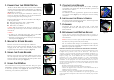
2. MAGNETIC STRIPE READER
Find the card reader slot at the right side of PIN Pad.
Slide the card in either direction through the slot without
stopping. If the card swipe fails, check the position of the
magnetic stripe and slide the card again. (Figure 4)
3. USING THE CARD READER
Find the card reader slot on bottom of PIN Pad. Please insert
the card completely and make sure that it cannot be moved
forward anymore. If inserted failed, check the position of the
card and insert the card again. (Figure 5)
4. USING THE PINPAD
Press numeral key to enter password if needed. Then press green
[ENTER] key to finish password key-in. Press red [CANCEL] key
to exit from presently status (Figure 6). If the PIN is entered
incorrectly, press yellow key and reenter it.
Figure 1
Figure 2
Figure 3
Figure 4
Figure 5
Figure 6
5. CONTACTLESS READER
Contactless reader is on the top of FD-35, FD-35-ZKA. It will light
up with blue color signal when FD-35, FD-35-ZKA is powered on
and that means reader is
working normally.
Put contactless card to approach the signal icon in the middle
area of card reader (Figure 7) for reading the card data during
transaction.
6. INSTALLING THE PRIVACY SHIELD
The privacy shield is installed on the device, and the keypad will
be separated from the LCD. (Figure 8)
7. CLEANING
Periodically clean the PIN Pad device with a clean cloth
dampened with water and a mild soap or cleaner. Do not use
harsh chemicals.
8. RETURNING THE PIN PAD DEVICE
If you need to return your PIN Pad device for service or
replacement, contact your service provider or sales representative
for instructions.
Note: Do not try to service, repair or adjust the PIN Pad device in
any other way; doing so will void your warranty.
You are cautioned that changes or modifications not expressly
approved by the party responsible for compliance could void your
authority to operate the equipment.
Federal Communication Commission Interference Statement
This equipment has been tested and found to comply with the limits for a Class
B digital device, pursuant to Part 15 of the FCC Rules. These limits are
designed to provide reasonable protection against harmful interference in a
residential installation. This equipment generates, uses and can radiate radio
frequency energy and, if not installed and used in accordance with the
instructions, may cause harmful interference to radio communications.
However, there is no guarantee that interference will not occur in a particular
installation. If this equipment does cause harmful interference to radio or
television reception, which can be determined by turning the equipment off and
on, the user is encouraged to try to correct the interference by one of the
following measures:
- Reorient or relocate the receiving antenna.
- Increase the separation between the equipment and receiver.
- Connect the equipment into an outlet on a circuit different from that to
which the receiver is connected.
- Consult the dealer or an experienced radio/TV technician for help.
FCC Caution: Any changes or modifications not expressly approved by the
party responsible for compliance could void the user's authority to operate this
equipment.
Figure 7
Figure 8