
User's Manual
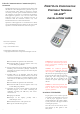

POWER ON TERMINAL
There are two connections under a
plastic cover on the left side of terminal
(Figure 1). The bottom is power input;
the other is a USB port for devices to
connect to terminal (Figure 2).
Adapter spec:
LI SHIN INT. / LSE0107A1240
Input: 100-240Vac, 50/60Hz 1A
Output: 12Vdc, 3.33A
Operating Temperature:
0
o
C to 40
o
C
Battery pack:
CHENG UEI / FD-400 7.4V, 2.3Ah
Car Charger:
EDAC POWER ELECRONICS CO.,
LTD. / ED1025
Input: 11-16Vdc, 5A
Output: 12Vdc, 2.5A
Rechargeable battery is at the bottom of
terminal (Figure 3).
Caution: The cover (Figure 3) shall be
provided with a means to keep it closed
during normal operation.
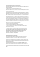
Plug the power cord or install the
battery, press the power button on the
front to power on it (Figure 4).
Table A1: Matrix of Observation Corridors and PIN Protection
Methods
Observation Corridors
Method Cashier
Customers Customers On-Site Remote
in Queue Elsewhere Cameras Cameras
PED Stand
A
M H L L L
PED Stand B H H H L M
Check-Stand
A
L M M L H
Check-Stand
B
H H M H H
Customer
Instruction
H* H* H* H* H*
* Customer Instruction methods are less repeatable and therefore should be
used in combination with other methods. L = low, M = medium, H = high.
Figure 1
Figure 2
Figure 3
Figure 4
1
6
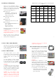
USING THE CARD READER
The reader slot is located at of terminal.
Swipe card through slot in left to right
or the opposite direction with stripe
face to us (Figure 8).
USING THE KEYPAD
The keypad allows you to select
transaction types and enter information.
It has 16 keys can be used to select
numbers, letters, and to enter data
(Figure 9).
To enter numbers or letters, simply
press the appropriate key. For example,
to type the letter A, press [ALPHA],
and then [A] (the Void key). (Figure 10)
Warning:
A shielded-type power cord is required
in order to meet FCC emission limits
and also to prevent interference to the
nearby radio and television reception.
Use only the power cord supplied.
Caution: Use only shielded signal
cables to connect I/O devices to this
equipment. You are cautioned that
changes or modifications not expressly
approved by the party responsible for
compliance could void your authority
to operate the equipment.
INSTALLING PRIVACY SHIELD
The privacy shield of the FD-400eTi
shows as Figure 11.
There are four slots along the perimeter
(Figure 12). Lock the privacy shield
around on the slots (Figure 13).
When the privacy shield is installed, the
keypad is separated into two part;
number keys are protected within the
shield (Figure 14).
Warning:
If the device, FD-400eTi, is used
without the detachable privacy shield,
the following criteria needs to be met
by the Installed Environment of the
PED for complying with the PCI
privacy screen design requirement:
A. Positioning of the PED on the
check-stand in such way as to make
visual observation of the PIN-entry
process infeasible.
Figure 11
Figure 12
Figure 13
Figure 14
Figure 8
Figure 9
Figure 10
3
4