INSTALLATION INSTRUCTIONS MODEL PA1235X 12 CHANNEL POWER AMPLIFIER TABLE OF CONTENTS Section Title Page SAFETY INSTRUCTIONS ....................................................................................................................................2 GENERAL INFORMATION...................................................................................................................................3 PA1235X PANEL AND FEATURE DESCRIPTIONS ...........................................................
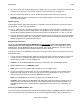
Page 2 Model PA1235X SAFETY INSTRUCTIONS - READ BEFORE OPERATING EQUIPMENT CAUTION: TO REDUCE THE RISK OF ELECTRIC SHOCK, DO NOT REMOVE COVER (OR BACK) NO USER-SERVICEABLE PARTS INSIDE REFER SERVICING TO QUALIFIED SERVICE PERSONNEL The lightning flash with arrowhead symbol, within an equilateral triangle, is intended to alert the user to the presence of un-insulated “dangerous voltage” within the product’s enclosure that may be of sufficient magnitude to constitute a risk of electric shock to persons.
Model PA1235X Page 3 GENERAL INFORMATION To enhance the ease of installation and obtain optimum performance from the PA1235X, we recommend that you first become familiar with all its features and special capabilities by studying the descriptions and instructions in this manual. The PA1235X was designed to meet the audio power amplifier needs of custom installed multi-zoned systems with high sonic quality.
Page 4 Model PA1235X Remote Master ON/OFF Jack. This jack allows the PA1235X to be powered on and off by a positive DC voltage ranging between 4 and 30 volts (11mA @ 12 V). Specifically, it permits the 12-volt common CO (Control Output) or zone STATUS outputs from the Xantech ZPR68 to power one or more PA1235X's ON and OFF automatically with zone ON/OFF commands.
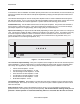
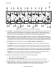
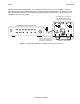
Model PA1235X Page 5 8 7 5 7 5 7 5 7 5 7 5 7 5 REFER TO OWNERS MANUAL FOR SAFETY INSTRUCTIONS. LEFT RIGHT 1 LEFT 2 MODE STEREO MONO BRIDGED 3V + BRIDGED -- 3V + BRIDGED -- SPEAKER -- SPEAKER RIGHT LEFT + -- -- + 1V .2V LEFT .2V 1V LEFT MODE STEREO MONO BRIDGED THE RISK OF FIRE OR ELECTRICAL SHOCK, DO NOT EXPOSE THIS UNIT TO RAIN, MOISTURE OR PLACE WATER FILLED OBJECTS ON THE PRODUCT. LEVEL NO USER SERVICABLE PARTS INSIDE.
Page 6 Model PA1235X CAUTION: When making connections for the BRIDGED mode, remember, only one speaker is being attached per amplifier pair. Be sure to observe the outer "+” and "–" polarity markings on each side of the word "BRIDGED" on the panel above the 4-terminal connector when connecting the 2-conductor wire to the speaker. 10. Remote Master On/Off Control.
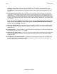
Model PA1235X Page 7 INSTALLATION - PHYSICAL LOCATION AND MOUNTING Upper shelf, component, wall, etc. Keep perforations on top cover free of PA1235X obstructions for max. cooling effect. To maximize air flow, route single large opening in lower shelf. 2-inch spacing (minimum) Convection Airflow Keep perforations on bottom plate free of obstructions. Figure 4 – PA1235X Horizontal Mounting When you mount the PA1235X, you should plan its location carefully.
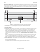
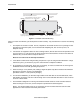
Page 8 Model PA1235X CONNECTING THE PA1235X Preamp Outputs ZPR68, etc. VIDEO RCA Type Patch Cords L Preamp Outputs ZPR68, etc. VIDEO RCA Type Patch Cords L AUDIO AUDIO R PA1235X Rear Panel Set MODE Switch to STEREO position 1 R Set MODE Switchs to BRIDGED position 1 PA1235X Rear Panel LEFT RIGHT 1 MODE STEREO MONO BRIDGED LEFT WARNING TURN POWER OFF BEFORE CHANGING MODES 1V .2V WARNING 1V LEVEL 3V + BRIDGED -- .
Model PA1235X Page 9 6. As a rule of thumb, use 18 gauge speaker wire for speaker runs up to 30' (9m), 16 gauge up to 70' (21m), and 14 gauge up to 150' (39m). The 4-terminal connectors accept wire sizes up to 12-gauge max. 7. Strip the insulation back about 1/4" (6mm) and twist the strands on each lead to prevent fraying.
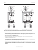
Page 10 Model PA1235X PA1235X can be switched ON and OFF via the switched AC outlet on the rear of a preamplifier. When the preamplifier Power Switch is switched ON, power is applied to the DC adapter, which in turn applies 5V to 30V DC to the PA1235X, switching it ON. Similarly, when the preamplifier is switched OFF, the DC voltage to the PA1235X is removed, turning it OFF.
Model PA1235X Page 11 A Multi-Zone System Diagram Using The PA1235X Fig. 8, following, shows the PA1235X in a typical multi-room system with a Xantech ZPR68-10 Six-Zone Preamp. In this case, the common +12V CO (control output) from the ZPR68-10 is used to remotely turn the PA1235X On and Off. When any one of the zones is turned on, the common +12V CO goes high, turning the PA1235X On. Similarly, when the last zone is turned OFF, the +12V CO drops to 0V and turns the PA1235X Off.
Page 12 Model PA1235X TROUBLE SHOOTING If you encounter a problem, please review the items in the following list. Be sure, in addition, to check other system components, such as preamplifiers, CD players, speakers, speaker wiring, etc., that may be at fault. PROBLEM PROBABLE CAUSE AND SOLUTION Rear panel Power Indicator does not light – no sound. Check line cord for good contact in a live AC outlet. If REMOTE ON/OFF jack is used, be sure applied voltage is between +5V and +30V DC with proper polarity.
Model PA1235X Page 13 SPECIFICATIONS Number of channels 12 Power Output 35 Watts at 8 Ohms Rated continuous power, each channel, all 12 channels simultaneously driven, 20 Hz to 20kHz, at rated THD Power Output 55 Watts at 8 Ohms 80 Watts at 4 Ohms Short term continuous, each channel, 2 channels driven, 1 kHz, at rated THD Bridged Power Output 150 Watts at 8 Ohms (80 Watts continuous) Short term continuous, one pair driven at 1 kHz, at rated THD Rated THD < 0.
Page 14 Model PA1235X © 2002 Xantech Corporation.
Model PA1235X Page 15 © 2002 Xantech Corporation.
XANTECH CORPORATION 12950 Bradley Avenue, Sylmar CA 91342-3829 phone 818.362.0353 • fax 818.362.9506 www.xantech.com Part No.