INSTALLATION INSTRUCTIONS MODEL PA435X FOUR CHANNEL POWER AMPLIFIER TABLE OF CONTENTS SectionTitle Page SAFETY INSTRUCTIONS - READ BEFORE OPERATING EQUIPMENT.........................................................................................................2 GENERAL INFORMATION .............................................................................................................................................................................3 PA435X PANEL AND FEATURE DESCRIPTIONS ............
Page 2 Model PA435X SAFETY INSTRUCTIONS - READ BEFORE OPERATING EQUIPMENT CAUTION: TO REDUCE THE RISK OF ELECTRIC SHOCK, DO NOT REMOVE COVER (OR BACK) NO USER-SERVICEABLE PARTS INSIDE REFER SERVICING TO QUALIFIED SERVICE PERSONNEL The lightning flash with arrowhead symbol, within an equilateral triangle, is intended to alert the user to the presence of un-insulated “dangerous voltage” within the product’s enclosure that may be of sufficient magnitude to constitute a risk of electric shock to persons.
Model PA435X Page 3 GENERAL INFORMATION To enhance the ease of installation and obtain optimum performance from the PA435X, we recommend that you first become familiar with all its features and special capabilities by studying the descriptions and instructions in this manual. The PA435X was designed to meet the audio power amplifier needs of custom installed multi-zoned systems with high sonic quality.
Page 4 Model PA435X Peak/Clip LED Indication: Whenever either amplifier channel output starts to enter a clipping state, a front panel LED will illuminate RED. After the amp stops clipping the LED will return to its normal state 5-6 seconds after clipping stops. Auto Protection Circuit. This feature protects the PA435X if a short or very low impedance is detected at the speaker terminals with each amplifier pair protected separately.
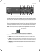
Model PA435X Page 5 PA435X PANEL AND FEATURE DESCRIPTIONS 1. Front Panel . 17" X 3.5” panel designed for shelf mounting. The unit measures 4” high with the Feet (Item #5). When rack mounting use an adequate rack shelf mount making sure to allow for proper ventilation. FIGURE 2 – THE MODEL PA435X FRONT PANEL – FEATURES AND FUNCTIONS 2.
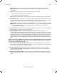
Page 6 Model PA435X 11 12 6 14 10 8 6 7 10 8 9 7 13 15 FIGURE 3 – PA435X REAR PANEL - FEATURES AND FUNCTIONS 6. Line Inputs. These RCA-type jacks are the audio inputs for each of the amplifier pairs. Connect them to the Preamp Output jacks of Zone 7 & 8 of the MRC88 (or other driving preamp output) with good quality RCA-type patch cables. Note that the inputs are marked LEFT-A-RIGHT, LEFT-B-RIGHT signifying the stereo channel pairs.
Model PA435X Page 7 CAUTION: Be sure to have the rear AC LINE POWER switch (Item #15) turned OFF (O) when changing the position of this switch and when making the corresponding speaker connection changes. 9. FUSE. When required, replace only with a fuse of the same type and rating: 120 V Version: 6.25 AMP 250 VAC, SLOW BLOW. 240 V Version: 3.15 A Time-Lag 250 VAC. NOTE: Replacement with a fuse of higher rating will not protect the amplifier and will void the warranty. 10. SPEAKER Terminals.
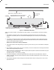
Page 8 Model PA435X INSTALLATION - PHYSICAL LOCATION AND MOUNTING Upper shelf, component, wall, etc. PA435X Keep perforations on top cover free of obstructions for max. cooling effect. To maximize air flow, route single large opening in lower shelf. 2-inch spacing (minimum) Convection Airflow Figure 5 – HORIZONTAL MOUNTING Keep perforations on bottom plate free of obstructions. When you mount the PA435X, you should plan its location carefully.
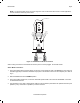
Model PA435X Page 9 NOTE: You should consider some sort of rear support for rack mounted units when used in mobile applications or when located in seismically-active areas. CONNECTING THE PA435X MRC88 Preamp Ouptus or Other PREAMP OUT 7 L R STATUS ZONE IR K E Y P A D PA435X Rear Panel Set MODE Switch to STEREO position RCA Type Patch Cords LEFT A RIGHT MODE STEREO MONO BRIDGED 1V LEVEL .
Page 10 Model PA435X 5. Be sure to observe correct polarity by connecting the "+" and "–" terminal from each channel on the PA435X to the corresponding "+" and "–" terminals on each speaker. This will ensure correct "phasing" - see Fig. 6 and Speaker Phasing below. Since the connectors are removable, you may unplug them for ease of lead assembly. 6. As a rule of thumb, use 18 gauge speaker wire for speaker runs up to 30' (9m), 16 gauge up to 70' (21m), and 14 gauge up to 150' (39m).
Model PA435X Page 11 MRC88 Preamp Ouptus or Other PREAMP OUT 8 L R STATUS ZONE IR RCA Type Patch Cord K E Y P A D RCA Type Patch Cord LEFT A Set MODE Switch to BRIDGED position RIGHT LEFT MODE STEREO MONO BRIDGED 1V RIGHT MODE STEREO MONO BRIDGED 1V LEVEL LEVEL .2V 3V + BRIDGED SPEAKER LEFT B PA435X Rear Panel .2V 3V -- + BRIDGED SPEAKER RIGHT LEFT + -- -- + -- RIGHT + -- -- + Be sure speakers are connected with correct polarity as shown.
Page 12 Model PA435X CAUTION: When operating in the BRIDGED mode (particularly when bench testing the amplifier) do not make a ground or any other kind of connection to the amplifier speaker terminals other than those to the individual speakers as shown. Failures caused by inappropriate connections are not covered under the warranty.
Model PA435X Page 13 A Multi-Zone System Diagram Using The PA435X and MRC88 Fig. 9, following, shows the PA435X in a typical multi-room system with a Xantech MRC88 eight-zone preamp. Use 3.5mm Stereo Mini Plug Cables RCA Type Patch Cords ZONE 7 ZONE 8 To Speakers in Rooms Figure 9: Interfacing the PA435X with an MRC88 Zones 7 & 8 In this case: 1.
Page 14 Model PA435X The Remote Amp CO1 & CO2 (Remote Control Jack) from the MRC88 allows for individual Zone control directly from the Zone 7 & 8 keypads of the MRC88 system. When any one of the zones is turned on, the PA435X is powered ON. Similarly, when either Zone is powered down, the associated amplifier pair on the PA435X is put into STANDBY Mode.
Model PA435X Page 15 TROUBLE SHOOTING If you encounter a problem, please review the items in the following list. Be sure, in addition, to check other system components, such as preamplifiers, CD players, speakers, speaker wiring, etc., that may be at fault. PROBLEM PROBABLE CAUSE AND SOLUTION Rear panel Power Indicator does not light – no sound. Check line cord for good contact in a live AC outlet.
Page 16 Model PA435X SPECIFICATIONS Number of channels 4 Power Output 35 Watts at 8 Ohms Rated continuous power, each channel, all six channels simultaneously driven, 20 Hz to 20kHz, at rated THD Power Output 55 Watts at 8 Ohms 80 Watts at 4 Ohms Short term continuous, each channel, 2 channels driven, 1 kHz, at rated THD Bridged Power Output 150 Watts at 8 Ohms Short term continuous, one pair driven at 1 kHz, at rated THD Rated THD < 0.
Model PA435X Page 17 © 2003 Xantech Corporation
Page 18 Model PA435X © 2003 Xantech Corporation
Model PA435X Page 19 © 2003 Xantech Corporation
Page 20 Model PA435X XANTECH CORPORATION 12950 Bradley Avenue, Sylmar CA 91342-3829 phone 818.362.0353 • fax 818.362.9506 www.xantech.com Part No.