
User's Manual


Model MRC88 Page: 27
© 2003 Xantech Corporation
NOTE 3: Program IR commands for the MRC44 Controller current sensing as described in the MRC44
Installation Instructions, “PROGRAMMING SENSE CODES”.
(EXPANDED)
Connect CSM1’s as described above to the Primary Controller. Sense inputs are not available on the
Secondary Controller.
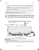
ZONE RELATED WIRING CONNECTIONS
In typical applications, each zone will have at least one MRC88 Keypad and a pair of stereo speakers. In
those zones with both audio and video, at least one video monitor or television will also be used. In order to
make these connections, the minimum requirement is home runs of one CAT5 cable for each zone’s
keypad(s), two pairs of 12-18AWG wire for each pair of speakers, and one coaxial cable for a TV or monitor
from each zone to the MRC88 Controller/Amplifier location.
S
PEAKER CONNECTIONS
(BASIC/ADVANCED/EXPANDED)
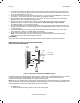
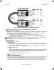
1. Using good quality speaker wire, connect the individual speaker leads to the 4-terminal "SPEAKER"
connectors on the MRC88 as shown in Figure 3-(22).
2. The MRC88 Speaker Terminals (amplifier outputs) are 4-Ohm safe. Make sure the combined
impedance presented to the speaker terminals by the speakers (or any combination of speakers) is 4-
Ohm minimum.
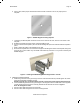
3. Be sure to observe correct polarity by connecting the "+" and "–" terminal from each channel on the
MRC88 to the corresponding "+" and "–" terminals on each speaker. This will ensure proper "phasing"
(See Step 6). Since the connectors are removable, you may unplug them for ease of lead assembly.
4. As a rule of thumb, use 18 gauge speaker wire for speaker runs up to 30' (9m), 16 gauge up to 70'
(21m), and 14 gauge up to 150' (39m). The 4-terminal connectors accept wire sizes up to 12-gauge
max.
5. Strip the insulation back about 1/4" (6mm) and twist the strands on each lead to prevent fraying.
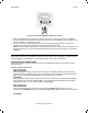
6. Speaker Phasing: To obtain stable imaging and full bass response, it is imperative that stereo
speakers be connected "in phase" with each other. You can verify this as follows:
a) If the "+" (positive) and "–" (negative) terminals on your speakers are correctly marked, and visible,
and you have wired the system with the positive connector on the rear of the MRC88
Controller/Amplifier connected to the positive connector on the speaker and the negative connector
on the rear of the MRC88 Controller/Amplifier connected to the negative connector on the speaker,
then the system will be "in phase". No further action is required. Most manufacturers identify the
positive terminal with a red binding post, a "+" sign, or a red dot.
b) If you are unsure of the markings, you can verify the phasing. Using a mono sound source, such as
AM radio, alternately reverse the leads to one of the speakers. Pick the connection that delivers a
solid center image between the speakers as well as best bass response.
CAUTION: After lead ends are inserted and the screws tightened down, be sure there are no free
strands that could cause shorting!