
User's Manual


Page: 28 Model MRC88
© 2003 Xantech Corporation
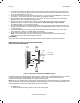
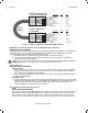
Wire Color Pin # Signal
white/orange 1 485 +
orange 2 485 -
white/green 3 12V RET
blue 4 IR RET
white/blue 5 IR
green 6 +12V
white/brown 7 Attn. 485
brown 8 IR Loop Back
Cat 5
Cable
RJ45 Connector at
Controller/Amplifier
RJ45 Connector
at Keypad
Wire Color Pin # Signal
white/orange 1 485 +
orange 2 485 -
white/green 3 12V RET
blue 4 IR RET
white/blue 5 IR
green 6 +12V
white/brown 7 Attn. 485
brown 8 IR Loop Back
Figure 10 - CAT5 Pin Assignments (per EIA/TIA 568B) Pinned 1:1
MRC88
KEYPAD CAT5 CABLE CONNECTIONS AT THE MRC88 CONTROLLER/AMPLIFIER
(BASIC/ADVANCED/EXPANDED)
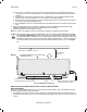
The MRC88 ‘Pin-to-Pin’ CAT5 cabling that can be purchased pre-fabricated at fixed lengths or self-assembled
to custom lengths. The color-coded wiring standard is EIA/TIA 568B as shown in Figure 10. The plastic
connector on the end of the CAT5 wire is “registered jack” RJ45.
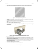
1. See Figure 10 for proper termination of the CAT5 cables to the RJ45 connectors.
2. Connect the zone keypad to the appropriate zone Keypad connector on the rear of the MRC88
Controller/Amplifier – Figure 3-(16).
Caution:
Power voltage for the keypad is transmitted along this cable! Incorrect wiring on this cable can destroy
the MRC Keypad! Be sure to test cable for proper connections before making connections.
V
IDEO CONNECTIONS
(BASIC/ADVANCED/EXPANDED)
Composite Video
1. When running composite video to a TV or monitor, use RG-6 coaxial or RG-59 quadshield cable with
RCA type phono plugs on each end. This connection can be run up to 150 feet, as this is a buffered
video output from the MRC88 Controller/Amplifier.
2. Connect the zone video cable to the appropriate zone video jack on the rear of the MRC88 Controller/
Amplifier – Figure 3-(18).
Modulated Video
3. When modulating the zone video output and using the RF/ANT input to a television, connect the VIDEO
OUTPUT from the MRC88 Controller – Figure 3-(18), to the VIDEO INPUT of a Modulator, using high
quality RCA type video patch cords. Use RG-6 coaxial cable with "F" connectors on each end to
connect the Modulator, to the RF/ANT IN on the room TV.
S
TATUS CONNECTIONS AND COMMON CONTROL OUT
Status
(BASIC/ADVANCED/EXPANDED)
Each zone has a Status Output –Figure 3-(19), that provides a control output of +12 VDC, 50mA that turns
ON and OFF with the zone ON/OFF condition. ON = +12VDC, OFF = 0VDC. Using a 3.5mm mono mini
phone connector, this control can be used to close a relay, such as a Xantech CC12, to raise a TV lift or
drop a projection screen automatically when a zone is turned ON. Connect one end of the 3.5mm Mono