
User's Manual


Page: 32 Model MRC88
© 2003 Xantech Corporation
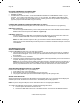
LINKING TWO MRC88 CONTROLLER/AMPLIFIER UNITS
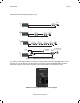
To connect two systems, simply connect the supplied DB15 Expansion Cable to the EXPANSION Port on the
rear of one unit to the EXPANSION Port on the other – Figure 3-(30). These units should be placed either side
by side or if installed in a 19” (483mm) equipment rack, leave 2 rack unit spaces (2U space) between the two
units [One Rack Unit space = 1-3/4” (44.5mm) in height].
CAUTION: Do not place these units directly on top of each other. This may cause damage to the units
due to increased heat dissipation.
C
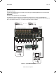
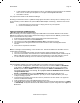
ONNECTING SOURCE COMPONENTS
When connecting two units together, designate one unit as the PRIMARY Unit (Zones 1-8) and the other unit as
the SECONDARY Unit (Zones 9-16). All source components should be connected directly to the PRIMARY
Units Source A/V Inputs – Figure 3-(22). Use the PRIMARY Units Audio and Video Loop-Thru connectors –
Figure 3-(23) to feed the source component inputs of the SECONDARY Unit – Figure 3-(22).
All of the source components emitters should be connected to the PRIMARY Units IR Emitter Output Ports –
Figure 3-(26). This rule applies to the SENSE INPUTS also.