INSTALLATION INSTRUCTIONS MRKP1E Keypad controller EU and UK Standard
Safety Information Xantech Limited Warranty Read Information — All the safety and operating information should be read before the appliance is operated. Follow Information — All operating and use information should be followed. Retain Information — The safety and operating information should be retained for future reference. Heed Warnings — All warnings on the appliance and in the operating instructions should be heeded.
Safety Check — Upon completion of any service or repairs to this audio product, ask the service technician to perform safety checks to determine that the audio product is in proper operating condition. Lightning Storms — Unplug this apparatus during lightning storms or when unused for long periods of time. Attachments and Accessories — Use only attachments/accessories specified by the manufacturer.
• • Do not install near any heat sources such as radiators, heat registers, stoves, or other apparatus (including amplifiers) that produce heat. In the unlikely event that smoke, abnormal noise, or strange odor is present, immediately power the MRKP1E off. Please report the problem to your dealer immediately. Never attempt to disassemble the MRKP1E. You will lose any product warranty on the unit. 6.
. Troubleshooting 1.0 Introduction Symptom Possible Cause Solution MRKP1E does not power up 1. RJ-45 plug crimped incorrectly; or wiring pin-out of RJ-45 reversed. Verify wiring pin-out and RJ-45 crimp. Correct by re-crimping RJ-45 to CAT-5 cable. 2. Break in CAT-5 between Zone and “Head-End”. Check RJ-45 to RJ-45 connections with cable tester or voltmeter. 1. Wiring: Incorrect wiring between MRKP1E and MRC88m. Verify and correct wiring. 2. IR emitter defective at source. Replace IR emitter.
Defining Terms Zone A Zone is defined as an area of the house that has separate source selection capabilities from all other areas of the house. Typically, a zone is comprised of a single room, but it is possible for a zone to spread across multiple rooms (kitchen/dining room, master bedroom/master bath) or for multiple zones to be contained in one room (game room/bar area or multiple zones in the yard). Fig. 4.
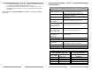
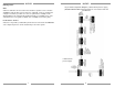
2.0 System Design Overview/Applications Fig. 4.1 Main Setup Menu Diagram (continued on next page) (MRC88m/MRAUDIO8X8m require Firmware Ver. 2.03 or later to work with the MRKP1E) Notes: A recommended electrical back box is always required for all installation of this product (see specifications). This keypad is specifically designed to work with the MRC88m and MRAUDIO8x8m (Firmware ver. 2.03 or later). It is NOT designed to work with MRC88, MRAUDIO8x8, MRC44, MRAUDIO4x4, or BXAUDIO4x4.
Pre-Wiring USER SETUP PARAMETERS CAT-5 Wiring between MRC88m and MRKP1E The MRC88m and all associated components are wired using CAT-5 terminated to the T568A or T568B Wiring Standard (Figure 2.1). When prewiring the system, run lengths of CAT-5 from the pre-determined MRC88m location to each Keypad or Touch Panel location. The CAT-5 cable routes all Power, Control, Communication, and IR information needed for full system operation. BALANCE Adjust audio output level on the right or left channel.
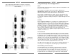
4. MRKP1E Main Setup Menu To access the Main Setup Menu, 1. Press and hold down the “X” key for at least 3 seconds. 2. Once the Main Setup Menu is displayed on the screen, use the “SOURCE <” and “SOURCE >” buttons to highlight the category to be changed. 3. Press the “X” button to choose the category. 4. Use the “SOURCE <” and “SOURCE >” buttons to highlight the parameter to be changed. 5. Use the “VOLUME UP” and “VOLUME DN” buttons to change the parameters. (For further details see diagram on Figure 4.
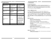
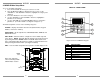
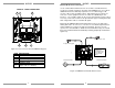
External IR Receiver Connections MRKP1E – REAR CONNECTORS 2 6 1 EXPANSION CONTROLLER Use an external Xantech IR Receiver in cases where a hand-held remote needs to be pointed somewhere other than at the MRKP1E or in cases where additional interference immunity requires the use of a different type of IR receiver or IR receiver mounting location. Typical IR Receiver locations are near a TV or other equipment such as a Local Source (DVD Player, A/V Receiver,…etc.).
Internal IR Receiver Installation The internal IR receiver is located beneath the center of the keypad’s face plate. The internal IR receiver receives IR commands for the MRKP1E and for the MRC88m. It will also pass-thru IR remote control commands to audio sources, via an emitter, to each of the sources connected to the MRC88m. The internal IR receiver is interference friendly. However, some optically noisy environments may require the use of an external IR receiver. (See Figure 3.
Note: Do not mount the MRKP1E in the same electrical back- box as high voltage devices such as electrical outlets or switches. 3. Connections MRKP1E to MRC88m and Expansion Keypads Each RJ-45 connector under each PREAMP OUT (1 – 8) is considered a “Zone port”. This Zone port interfaces with MRKP1E Keypad through CAT-5 cables. These connectors carry command/control information between the keypad and the MRC88m.