
User's Manual


9
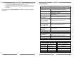
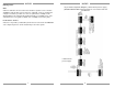
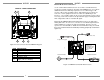
MRKP1E – REAR CONNECTORS
Figure 2.3: Rear connector board of MRKP1E Keypad
ITEM DESCRIPTION
1 Expansion RJ-45 Port
2 Controller RJ-45 Port
3 External IR Input terminal
4 RS485 termination
5 IR Emitter output
6
Internal IR Sensor Enable/Disable
jumper (remove to Disable)
3
1
2
5
6
4
EXPANSION CONTROLLER
14
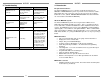
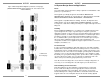
External IR Receiver Connections
Use an external Xantech IR Receiver in cases where a hand-held remote
needs to be pointed somewhere other than at the MRKP1E or in cases where
additional interference immunity requires the use of a different type of IR
receiver or IR receiver mounting location. Typical IR Receiver locations are
near a TV or other equipment such as a Local Source (DVD Player, A/V
Receiver,…etc.). A CAT-5 cable can be used to extend the IR receiver’s wire, if
necessary. Refer to the bottom of the Specifications page for wiring instruction
when using CAT-5 cable to extend the IR signal..
By default, the MRKP1E External and Internal IR receivers are both active.
Having both active, in some cases, can cause issues with IR signal reflection
and/or multiple processing of the same IR command. Therefore, in such
specific cases it is advisable to disable the Internal IR when using an external
IR receiver (Internal IR can be disabled by removing jumper clip on item #6 of
Figure 2.3).
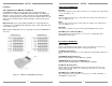
Figure 3.2: MRKP1E to External IR Connections
Xantech External IR
receiver
Xantech IR Emitter
To Expansion Keypad
To MRC88m Zone Port
NOTE: See polarity
markings near
connecting block for
proper wiring of IR
receiver and IR
emitter