
User's Manual


13
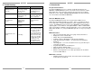
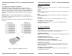
Internal IR Receiver
The internal IR receiver is located beneath the center of the keypad’s face
plate. The internal IR receiver receives IR commands for the MRKP1E and for
the MRC88m. It will also pass-thru IR remote control commands to audio
sources, via an emitter, to each of the sources connected to the MRC88m. The
internal IR receiver is interference friendly. However, some optically noisy
environments may require the use of an external IR receiver. (See Figure 3.2
for details on using an external IR receiver)
Figure 3.1: Internal IR Receiver
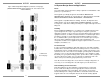
Compatible Handheld remotes
The MRKP1E’s minimal design necessitated the presence of a minimum
number of buttons. As a result, a handheld remote controller, such as a
Xantech RC68 or MREM is required for accessing other control functions of the
source such as navigation, menu, and transport controls. Other programmable
Xantech remotes such as XTR39 can also be used. The list of RC68 codes is
available at www.xantech.com/Controls/KeypadsRemotes/Remotes/MREM, in
the Products page, under “MREM Code List”.
(Note: RC68 commands may not be used with projects created in Quick
Config
TM
)
1
10
Installation
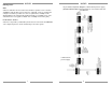
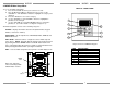
The MRKP1E is designed to mount in a standard single-gang electrical back-
box (J Box – see Specifications sections for details). Typical mounting height is
56-60 inches (1.53 meters) from the floor to the bottom of the frame. This
provides optimum viewing for the largest number of people.
Route the CAT-5 cable from the MRC88m into the back of the electrical back-
box, terminate it with an RJ-45 connector after it is passed through the
electrical back-box. Connect them to the appropriate RJ-45 connector on the
rear of the MRKP1E (“CONTROLLER” for connecting to MRC88m, or
“EXTENSION” if connecting to an extension keypad). If using an IR Receiver,
strip the ends of three conductors of the IR receiver’s cable and insert into the
appropriate terminals of the IR Input terminal block shown in Figure 3.2.
Once connections are made, mount the MRKP1E in to the electrical back-box
using the two provided screws. Mount the Trim Plate Bracket as shown in the
Figure 2.5 on the next page, and then snap the Screw-less Trim Plate in place.
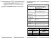
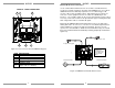
Figure 2.4: MRC88m – MRKP1E Pin-out diagram for Cat-5 cable
(T568B configuration)
Wire Color Pin # Signal
white/orange 1 485 +
orange 2 485 -
white/green 3 12V RET
blue 4 IR RET
white/blue 5 IR
green 6 +12V
white/brown 7 Attn. 485
brown 8 IR Loop Back
Cat 5
Cable
RJ45 Connector at
Controller/Amplifier
RJ45 Connector
at Keypad
Wire Color Pin # Signal
white/orange 1 485 +
orange 2 485 -
white/green 3 12V RET
blue 4 IR RET
white/blue 5 IR
green 6 +12V
white/brown 7 Attn. 485
brown 8 IR Loop Back