
User's Manual


11
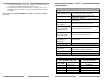
Note: Do not mount the MRKP1E in the same electrical back- box as high
voltage devices such as electrical outlets or switches.
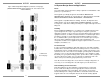
Figure 2.5: MRKP1E Keypad Installation
(See specifications)
12
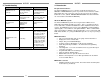
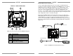
3. Connections
MRKP1E to MRC88m and Expansion Keypads
Each RJ-45 connector under each PREAMP OUT (1 – 8) is considered a “Zone
port”. This Zone port interfaces with MRKP1E Keypad through CAT-5 cables.
These connectors carry command/control information between the keypad and
the MRC88m. Connect CAT-5 cables terminated to an RJ-45 connector from
each Keypad to the corresponding RJ45 connector of the MRC88m as shown
below. (See Specifications section for maximum length of Cat-5 cables)
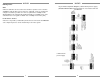
Figure 3.0: MRKP1E to MRC88m with expansion keypads
Note: Four keypads maximum per zone. Remove termination jumper on all
keypads except for the last keypad (see item #4 on Fig 2.3). Each expansion
keypad must each have its own unique address. (see Inst. Setup Menu on
Section 4 of this manual)
MRKP1E Rear
Zone 4
IR emitter
Zone 1
IR emitter
MRKP1E Rear
MRKP1E Rear
MRKP1E
R
ear
MRC88m Rear
Zone 1
Zone 2
Zone 8
MRKP1E Rear
MRKP1E Rear
RJ45 Zone
ports