by XPower Inverter 1000 Owner’s Guide
About Xantrex Xantrex Technology Inc. is a world-leading supplier of advanced power electronics and controls with products from 50 watt mobile units to one MW utility-scale systems for wind, solar, batteries, fuel cells, microturbines, and backup power applications in both grid-connected and stand-alone systems. Xantrex products include inverters, battery chargers, programmable power supplies, and variable speed drives that convert, supply, control, clean, and distribute electrical power.
About This Guide Purpose The purpose of this Owner’s Guide is to provide explanations and procedures for installing, operating, maintaining, and troubleshooting the XPower Inverter 1000. Scope The Guide provides safety guidelines, detailed planning and setup information, procedures for installing the inverter, as well as information about operating and troubleshooting the unit. It does not provide details about particular brands of batteries.
About This Guide Conventions Used The following conventions are used in this guide. WARNING Warnings identify conditions that could result in personal injury or loss of life CAUTION Cautions identify conditions or practices that could result in damage to the unit or other equipment. Important: These notes describe things which are important for you to know, but not as serious as a caution or warning. Related Information You can find more information about Xantrex Technology Inc.
Important Safety Instructions WARNING This chapter contains important safety and operating instructions. Read and keep this Owner’s Guide for future reference. 1. Before installing and using the XPower Inverter 1000, read all instructions and cautionary markings on the XPower Inverter 1000, the batteries, and all appropriate sections of this guide. 2. Do not expose the XPower Inverter 1000 to rain, snow, spray, or bilge water.
Safety Explosive gas precautions WARNING: Explosion hazard 1. Working in the vicinity of lead-acid batteries is dangerous. Batteries generate explosive gases during normal operation. Therefore, you must read this guide and follow the instructions exactly before installing or using your XPower Inverter 1000. 2. This equipment contains componentnts which tend to produce arcs or sparks.
Safety Precautions When Working With Batteries WARNING: Explosion or fire hazard 1. Follow all instructions published by the battery manufacturer and the manufacturer of the equipment in which the battery is installed. 2. Make sure the area around the battery is well ventilated. 3. Never smoke or allow a spark or flame near the engine or batteries. 4. Use caution to reduce the risk or dropping a metal tool on the battery.
Safety Precautions for Using Rechargeable Appliances CAUTION: Equipment damage The output of the inverter is non-sinusoidal. Most rechargeable battery-operated equipment uses a separate charger or transformer that is plugged into an AC receptacle and produces a low voltage charging output. Some chargers for small rechargeable batteries can be damaged if connected to the XPower Inverter 1000.
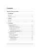
Contents Important Safety Instructions - - - - - - - - - - - - - - - - - - - - - - - - - - - - - - - - - - -v 1 Introduction Quality Power - - - - - - - - - - - - - - - - - - - - - - - - - - - - - - - - - - - - - - - - - - - - - - - - 1–1 Ease of Use - - - - - - - - - - - - - - - - - - - - - - - - - - - - - - - - - - - - - - - - - - - - - - - - - - 1–2 Comprehensive Protection - - - - - - - - - - - - - - - - - - - - - - - - - - - - - - - - - - - - - - - - 1–2 2 Features Materials List - - - - - - - - - - -
4 Operation Turning the Inverter On and Off - - - - - - - - - - - - - - - - - - - - - - - - - - - - - - - - - - - - 4–1 Operating Several Loads at Once - - - - - - - - - - - - - - - - - - - - - - - - - - - - - - - - - - - 4–2 Turning the Inverter Off Between Charges - - - - - - - - - - - - - - - - - - - - - - - - - - - - - 4–2 Operating Limits - - - - - - - - - - - - - - - - - - - - - - - - - - - - - - - - - - - - - - - - - - - - - - 4–3 Power Output - - - - - - - - - - - - - - - - - - - - - - - - - - - - -
Contents Battery Tips - - - - - - - - - - - - - - - - - - - - - - - - - - - - - - - - - - - - - - - - - - - - - - - - - -B–7 C Alternators and Charging Systems Charging System Requirements - - - - - - - - - - - - - - - - - - - - - - - - - - - - - - - - - - - -C–1 Charging With an Engine Alternator - - - - - - - - - - - - - - - - - - - - - - - - - - - - - - - - -C–2 Using a Standard Vehicle Alternator - - - - - - - - - - - - - - - - - - - - - - - - - - - - - -C–2 Using an Alternator Controller - - - - - -
xii
1 Introduction Congratulations on your purchase of the XPower Inverter 1000! The XPower Inverter 1000 has been designed to give you quality power, ease of use, and reliability. Please take a few moments to read this chapter to familiarize yourself with the main performance features and protection features of the XPower 1000. Quality Power The XPower 1000 is a quality inverter designed for recreational vehicle (RV) and truck applications.
Introduction Ease of Use Superior features and rugged durability have been combined with ease of use: • • The XPower 1000 is compact, light weight, and easy to install. Loads can be powered directly from the AC outlets. Comprehensive Protection The XPower 1000 is equipped with numerous protection features to guarantee safe and trouble-free operation: Low battery alarm 11.0 V or lower.
2 Features Chapter 2 describes the main features of the XPower 1000. Xantrex recommends that you familiarize yourself with them before installing and operating the inverter. Materials List Your XPower 1000 package includes: • • • • One XPower 1000 inverter Two M6 lock washers (on the DC input cable terminals) Two M6 nuts (on the DC input cable terminals) Owner’s Guide If any of these materials are missing or are unsatisfactory in any way, please contact Customer Service.
Features AC Panel 3 2 4 5 1 6 Figure 2-1 AC Panel Feature 2–2 Description 1 On/Off Switch turns the inverter’s control circuit on and off. This switch is not a power disconnect switch. Disconnect AC and DC power before working on any circuits connected to the inverter. 2 Power light is a green light indicating the On/Off Switch is on and AC voltage is present at the inverter’s AC outlets.
DC Panel DC Panel 3 4 2 5 1 6 Figure 2-2 DC Panel Feature 975-0127-01-01 Description 1 Chassis Ground Screw connects to vehicle chassis, DC grounding bus or to engine’s negative bus. 2 Positive DC Cabling Terminal always connects to the cable connected to the positive terminal of the battery. 3 Negative DC Cabling Terminal always connects to the cable connected to the negative terminal of the battery. 4 Ventilation Opening must not be obstructed for the proper operation of the inverter.
2–4
3 Installation Chapter 3 provides information on cables and fuses to help you plan for your installation and provide procedures for installing the XPower 1000. Xantrex highly recommends that you read the entire chapter before beginning the installation procedures so that you can plan an installation that is suited to your power needs.
Installation Figure 3-1 Configuration for Normal Loads 3–2 975-0127-01-01
Designing Your Installation Figure 3-2 Configuration for Heavy Loads 975-0127-01-01 3–3
Installation Installation Codes Governing installation codes vary depending on the location and type of installation. Electrical installations must meet local and national wiring codes and should be performed by a qualified electrician. In residential applications, electrical codes do not allow permanent connection of AC distribution wiring to the inverter’s AC output receptacles. The receptacles are intended for temporary (as-needed) connection of cord connected loads only.
Designing Your Installation Choosing an Appropriate Location WARNING: Explosion or fire hazard The XPower 1000 contains components that tend to produce arcs or sparks. To prevent fire or explosion, do not install the inverter in compartments containing batteries or flammable materials, or in locations that require ignition-protected equipment. WARNING: Fire hazard To reduce the risk of fire, do not cover or obstruct the ventilation openings. Do not install the XPower 1000 in a zero-clearance compartment.
Installation Calculating Cable Sizes To operate safely and effectively, the XPower 1000 needs proper cables and fuses. Because the XPower 1000 has low-voltage and high-current input, it is essential that you use low-resistance wiring between the battery and the inverter to deliver the maximum amount of usable energy to your load.
Designing Your Installation Table 3-1 Recommended DC Input Wire Sizes & Lengths RVa(Recreational Vehicle) Cable length: Battery to inverter (one way) Minimum Cable Size Maximum Battery Fuse Size Less than 5 feet (1.5 m) No. 2 AWG 150 ADC Note: Never use a cable longer than 5 feet (1.5 m) with the XPower 1000. Appropriately sized cable can be bought at a welding supply house or a marine supply store. a.
Installation Calculating Fuse/Circuit Breaker Size Because your batteries can provide thousands of amps of short-circuit current, you need fuses or circuit breakers that can safely withstand the short-circuit current that the batteries can produce. To select the correct fuse type and size: 1. Determine the total short-circuit current rating for your batteries.
Installing the XPower 1000 Installing the XPower 1000 Do not proceed with the installation of your XPower 1000 until you have read the section, “Designing Your Installation” on page 3–1. The more thorough your planning, the better your power needs will be met to achieve maximum performance from your XPower 1000. Safety Instructions Before you start to install the XPower 1000: • • • Review the “Important Safety Instructions” on page v.
Installation Materials The following checklist is a general list of required materials.
Installing the XPower 1000 Overview of Installation Steps These are the three steps for installing your XPower 1000. Do not proceed with installation until you have read “Designing Your Installation” on page 3–1. 1. Mount the inverter. 2. Connect the chassis ground. 3. Connect the DC cables. Mounting the Inverter Do not mount the inverter under the hood of your vehicle. See “Choosing an Appropriate Location” on page 3–5. To mount the XPower 1000: 1. Make sure the On/Off switch is in the Off position. 2.
Installation Connecting the Chassis Ground WARNING: Shock hazard Never operate the XPower 1000 without properly connecting the chassis ground. Electrical shock hazard could result from improper grounding. The XPower 1000 has a screw terminal labelled CHASSIS GND on the rear panel as shown in Figure 3-3 on page 3–12. Follow the guidelines in “Grounding Locations” to connect the inverter’s chassis to the ground.
Installing the XPower 1000 Chassis Ground Screw Xantrex recommends that you attach the cable to the chassis ground screw with a ring terminal. This procedure will ensure that the wire does not slip off the chassis ground screw. To connect the cable to the chassis ground screw: 1. Make sure the inverter’s On/Off switch is in the Off position. 2. Remove chassis ground screw and star washer using #2 Phillips screwdriver. 3. Strip 1/2 inch (13 mm) to 3/4 inch (19 mm) of insulation from one end of each cable.
Installation 4. For each cable end that will be connected to the inverter, strip 1/2 inch (13 mm) to 3/4 inch (19 mm) of insulation from the cable. The amount stripped off will depend on the terminals chosen. 5. Attach the connector that will join the cable to the DC cabling terminal. 6. Install a fuse and fuse holder in the cable that will be used for the positive side of the DC circuit.
Installing the XPower 1000 10. Before proceeding, double check that the cable you have just installed connects the positive DC terminal of the inverter to the Disconnect/ Battery Selector Switch, fuse holder, and that the other end of the fuse holder is connected to the positive terminal on the battery. . WARNING: Explosion or fire Do not complete the next step if flammable fumes are present. Explosion or fire may result if the Disconnect/Battery Selector switch is not in the Off position.
3–16
4 Operation Chapter 4 explains how to operate the XPower 1000 efficiently and effectively. Specifically, this chapter: • • • • Gives procedures for operating the inverter from the front panel Discusses operating limits and inverter loads Discusses battery charging frequency Provides information about routine maintenance Turning the Inverter On and Off The On/Off switch on the inverter’s front panel turns the control circuit in the XPower 1000 on and off.
Operation Operating Several Loads at Once If you are going to operate several loads from the XPower 1000, turn them on one at a time after you have turned the inverter on. Turning loads on separately helps to ensure that the inverter does not have to deliver the starting current for all the loads at once, and will help prevent an overload shutdown.
Operating Limits Operating Limits Power Output The XPower 1000 can deliver up to 1000 watts continuous. The wattage rating applies to resistive loads such as incandescent lights. Input Voltage The allowable XPower 1000 input voltage ranges are shown in the following table: 975-0127-01-01 Operating Condition Voltage Range Normal 10.5 V–15.0 V Optimum Performance 12.0 V–13.0 V Low Voltage Alarm 11.0 V or less Low Voltage Shutdown less than 10.
Operation Inverter Loads The XPower 1000 will operate most AC loads within its power rating of 1000 watts. However, some appliances and equipment may be difficult to operate, and other appliances may actually be damaged if you try to operate them with the XPower 1000. Please read “High Surge Loads” and “Trouble Loads” carefully. High Surge Loads Some induction motors used in freezers, pumps, and other motor-operated equipment require high surge currents to start.
Routine Maintenance Routine Maintenance XPower 1000 unit Minimal maintenance is required to keep your XPower 1000 operating properly. Periodically you should: • • • Clean the exterior of the unit with a damp cloth to prevent the accumulation of dust and dirt. Ensure that the DC cables are secure and fasteners are tight. Make sure the ventilation openings on the DC panel and bottom of the inverter are not clogged.
4–6
5 Troubleshooting Chapter 5 will help you identify the source of most problems that can occur with the XPower 1000. If you have a problem with the inverter, please review this chapter before contacting Xantrex Customer Service. If you are unable to solve a problem and need to contact Xantrex, record the details on the form “Information About Your System” on page WA–6. This will help our Customer Service Representatives give you better service.
Troubleshooting Common Problems Buzz in Audio Equipment Some inexpensive stereo systems may emit a buzzing noise from their loudspeakers when operated from the XPower 1000. This occurs because the power supply in the audio system does not adequately filter the modified sine wave produced by the inverter. The only solution is to use a sound system that has a higher quality power supply. Television Reception When the XPower 1000 is operating, it can interfere with television reception on some channels.
Troubleshooting Reference Troubleshooting Reference WARNING: Electrical Shock and Burn Hazard Do not disassemble the XPower 1000. It does not contain any user-serviceable parts. Attempting to service the unit yourself could result in an electrical shock or burn. Table 5-1 Troubleshooting Reference Problem Possible Cause Low output voltage (96 VAC–104 VAC) You are using a voltmeter that Use a true RMS reading voltmeter such as the Fluke 87.
Troubleshooting Table 5-1 Troubleshooting Reference Problem Possible Cause Solution No output voltage. Fault Light is on. Low input voltage Recharge the battery; check the connections and cable. High input voltage Make sure the XPower 1000 is connected to a 12 V battery. Check the voltage regulation of the charging system. Thermal shutdown Allow the unit to cool off. Reduce the load if continuous operation is required. Improve ventilation.
A Specifications Appendix A contains electrical performance and physical specifications for the XPower 1000. Electrical Performance Electrical performance XPower 1000 Output power at 77 º F (25 ºC) ambient temperature and 12 VDC input: • Maximum continuous output power • 5 minutes 1000 W 1200 W Output voltage 115 VAC RMS ± 5% Output waveform Modified sine wave Output frequency 60 Hz ± 4 Hz Input voltage 10.5–15.0 VDC Low voltage alarm 11.0 V Low voltage cutout 10.
Specifications Mounting Templates A–2 975-0127-01-01
B Battery Types The information in Chapter B will help you to select, connect, and maintain batteries that are most appropriate for your application. The batteries that you use strongly affect the performance of the XPower 1000. It is important to connect the inverter to the correct size and type of battery. Battery Types Automotive Starting Batteries The lead-acid battery you are most familiar with is probably the starting battery in your vehicle.
Battery Types Deep-Cycle Batteries Deep-cycle batteries are designed for deep discharge service where they will be repeatedly discharged and recharged. They are marketed for use in recreational vehicles, boats, and electric golf carts—so you may see them referred to as RV batteries, marine batteries, or golf cart batteries. For most applications of the XPower 1000, Xantrex recommends that you use one or more deep-cycle batteries that are separated from the vehicle’s starting battery by a battery isolator.
Battery Size Battery Reserve Capacity Battery reserve capacity is a measure of how long a battery can deliver a certain amount of current—usually 25 amps. For example, a battery with a reserve capacity of 180 minutes can deliver 25 amps for 180 minutes before it is completely discharged. Amp-hour (Ah) Capacity Amp-hour capacity is a measure of how many amps a battery can deliver for a specified length of time—usually 20 hours.
Battery Types Estimating Battery Requirements To determine how much battery capacity you need: 1. Determine how many watts are consumed by each appliance that you will operate from the XPower 1000. You can normally find the watt rating labelled on the product. If only the current draw is given, multiply it by 115 to get the power consumption in watts. 2. Estimate how many hours each appliance will be operating each day. 3. Calculate the daily watt-hours needed for each appliance. 4.
Estimating Battery Requirements This example illustrates how quickly your battery needs can escalate. To reduce the required battery size, you can conserve energy by eliminating or reducing the use of some loads or by re-charging more frequently. When sizing your battery, resist the temptation to skip the last step of this calculation (multiplying by 2).
Battery Types Using Multiple Batteries As your power requirements increase, you may need to use more than one battery to obtain sufficient capacity. Read “Two Batteries Connected In Parallel” and “Two Separate Battery Banks” to determine whether two batteries or two battery banks are more appropriate for your applications. Two Batteries Connected In Parallel Two identical batteries can be connected positive (+) to positive (+) and negative (–) to negative (–) in a parallel system.
Battery Tips Battery Tips WARNING Review “Precautions When Working With Batteries” on page vii before you work with the batteries in your system. Explosive/ Corrosive Gases Temperature Sensitivity Lead-acid batteries may emit hydrogen gases, oxygen, and sulfuric acid fumes when recharging. To reduce the risk of explosion: • • Vent the battery compartment to prevent the accumulation of gases. Do not install electronic or electrical equipment in the battery compartment.
Battery Types Battery Connections Connections to battery posts must be made with permanent connectors that provide a reliable, low-resistance connection. Do not use alligator clips. Clean the connections regularly and prevent corrosion by using a protective spray coating or Vaseline. Battery State of Charge You can measure battery state of charge with a hydrometer or approximate state of charge with a voltmeter.
C Alternators and Charging Systems Appendix C provides guidelines for recharging batteries from an alternator, from AC power, and from alternate energy sources. A good charging system is important for the health of your batteries. Poor recharging methods can quickly damage batteries. Charging System Requirements Your charging system should be capable of delivering a charging current equal to 25% of the amp-hour capacity of your battery.
Alternators and Charging Systems Charging With an Engine Alternator Read the following information to determine whether your vehicle’s standard alternator will be adequate by itself, whether you should install an alternator controller, or whether you need a high-output alternator. Using a Standard Vehicle Alternator A typical engine alternator (12 volts) may not be able to meet the requirements outlined above if your system uses large capacity batteries.
Charging From AC Power Charging From AC Power When recharging from AC power, use a good quality marine battery charger or RV converter that meets the requirements outlined in “Charging System Requirements” on page C–1. For information about Xantrex’s battery chargers, visit our web site at www.xantrex.com or call Customer Service on page ii. Do not use chargers intended for occasional recharging of automotive starting batteries. These chargers are not intended for continuous use.
C–4
Warranty and Return Information Warranty What does this warranty cover? This Limited Warranty is provided by Xantrex Technology, Inc. ("Xantrex") and covers defects in workmanship and materials in your XPower Inverter 1000. This warranty period lasts for 90 days from the date of purchase at the point of sale to you, the original end user customer. You require proof of purchase to make warranty claims.
Warranty and Return What proof of purchase is required? In any warranty claim, dated proof of purchase must accompany the product and the product must not have been disassembled or modified without prior written authorization by Xantrex.
Warranty and Return Disclaimer Product THIS LIMITED WARRANTY IS THE SOLE AND EXCLUSIVE WARRANTY PROVIDED BY XANTREX IN CONNECTION WITH YOUR XANTREX PRODUCT AND IS, WHERE PERMITTED BY LAW, IN LIEU OF ALL OTHER WARRANTIES, CONDITIONS, GUARANTEES, REPRESENTATIONS, OBLIGATIONS AND LIABILITIES, EXPRESS OR IMPLIED, STATUTORY OR OTHERWISE IN CONNECTION WITH THE PRODUCT, HOWEVER ARISING (WHETHER BY CONTRACT, TORT, NEGLIGENCE, PRINCIPLES OF MANUFACTURER'S LIABILITY, OPERATION OF LAW, CONDUCT, STATEMENT OR OTHERWISE
Warranty and Return Return Material Authorization Policy Before returning a product directly to Xantrex you must obtain a Return Material Authorization (RMA) number and the correct factory "Ship To" address. Products must also be shipped prepaid. Product shipments will be refused and returned at your expense if they are unauthorized, returned without an RMA number clearly marked on the outside of the shipping box, if they are shipped collect, or if they are shipped to the wrong location.
Warranty and Return Out of Warranty Service If the warranty period for your XPower Inverter 1000 has expired, if the unit was damaged by misuse or incorrect installation, if other conditions of the warranty have not been met, or if no dated proof of purchase is available, your inverter may be serviced or replaced for a flat fee.
Warranty and Return Information About Your System As soon as you open your XPower Inverter 1000 package, record the following information and be sure to keep your proof of purchase. ❐ Serial Number (on DC end) _________________________________ ❐ Purchased From _________________________________ ❐ Purchase Date _________________________________ If you need to contact Customer Service, please record the following details before calling.