XPH 18-10 Operating Manual XPH Series 18V 10A DC Power Supply
About Xantrex Xantrex Technology Inc. is a world-leading supplier of advanced power electronics and controls with products from 50 watt mobile units to one MW utility-scale systems for wind, solar, batteries, fuel cells, microturbines, and backup power applications in both grid-connected and stand-alone systems. Xantrex products include inverters, battery chargers, programmable power supplies, and variable speed drives that convert, supply, control, clean, and distribute electrical power.
Introduction The XPH 18-10 is an exceptionally compact and lightweight single output laboratory dc power supply providing 0 to 18V at 0 to 10A. The XPH 18-10 uses mixed−mode regulation technology which combines switch−mode pre−regulation with linear post−regulation. Special techniques are used to maintain very high efficiency whilst achieving noise levels that are close to that of a pure linear regulator. Excellent line and load regulation are matched by low noise and good transient response.
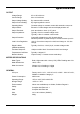
Specification OUTPUT Voltage Range: 0V to 18V minimum Current Range: 0A to 10A minimum Output Voltage Setting: By coarse and fine controls. Output Current Setting: By single logarithmic control. Operating Mode: Constant voltage or constant current with automatic cross-over. Output Switch: Electronic. Preset voltage and current displayed when off. Output Terminals: 4mm terminals on 19mm (0.75”) pitch. Output Impedance: Typically <5mΩ in constant voltage mode.
Safety This power supply is a Safety Class I instrument according to IEC classification and has been designed to meet the requirements of EN61010-1 (Safety Requirements for Electrical Equipment for Measurement, Control and Laboratory Use). It is an Installation Category II instrument intended for operation from a normal single phase supply. This instrument has been tested in accordance with EN61010-1 and has been supplied in a safe condition.
EMC This instrument has been designed to meet the requirements of the EMC Directive 89/336/EEC. Compliance was demonstrated by meeting the test limits of the following standards: Emissions EN61326 (1998) EMC product standard for Electrical Equipment for Measurement, Control and Laboratory Use. Test limits used were: a) Radiated: Class B b) Conducted: Class B c) Harmonics: EN61000-3-2 (2000) Class A; the instrument is Class A by product category.
Installation Mains Operating Voltage Check that the instrument operating voltage marked on the rear panel is suitable for the local supply. Mains Lead When a three core mains lead with bare ends is provided this should be connected as follows: BROWN - MAINS LIVE BLUE - MAINS NEUTRAL GREEN/YELLOW - EARTH Safety Earth Symbol When fitting a fused plug a 5 amp fuse should be fitted inside the plug.
Operation Setting Up the Output With the POWER switch on (l) and the output off the output voltage and current limit can be accurately preset using the VOLTAGE and CURRENT controls; the left-hand meter shows the set voltage and the right-hand meter shows the set maximum current. When the output switch is switched on, the ON lamp lights; the left-hand meter now shows the actual voltage and the right-hand meter the actual load current.
Series or Parallel Connection with Other Outputs The outputs of the power supply are fully floating and may be used in series with other power supply units to generate high DC voltages up to 300V DC. The maximum permissible voltage between any terminal and earth ground ( ) is 300VDC. WARNING! Such voltages are exceedingly hazardous and great care should be taken to shield the output terminals for such use. On no account should the output terminals be touched when the unit is switched on under such use.
Calibration Allow at least 5 minutes warm-up before commencing calibration. Access to Calibration Adjustments All adjustments are on the front panel control board; all the trimmers are adjusted from the reverse side of the board through holes in the board. To gain access to the board it is necessary to remove the top cover. WARNING! When the instrument is connected to its supply the removal of covers is likely to expose live parts.
Voltage Calibration Set the sense switch to local. Connect the DMM (set to Volts) across the output. Set voltage and current controls to minimum. Switch output ON (Check LED is on) and check for a reading of 00.00V ± 0.01V on the Volts display and DMM; check the Amps display reads 0.00 ± 0.01A. Set voltage and current controls to maximum. Adjust VR5 (maximum output volts) for a reading of 18.05V to 18.10V on the DMM.
Sécurité Cet instrument est de Classe de sécurité 1 suivant la classification IEC et il a été construit pour satisfaire aux impératifs EN61010-1 (impératifs de sécurité pour le matériel électrique en vue de mesure, commande et utilisation en laboratoire). Il s'agit d'un instrument d'installation Catégorie II devant être exploité depuis une alimentation monophasée habituelle. Cet instrument a été soumis à des essais conformément à EN61010-1 et il a été fourni en tout état de sécurité.
Installation Tension d’utilisation secteur Vérifier que la tension opérationnelle de l'instrument indiquée sur le panneau arrière est appropriée pour l'alimentation locale. Câble secteur Relier de la manière suivante tout câble secteur à trois conducteurs à fils nus: MARRON - SECTEUR SOUS TENSION BLEU - SECTEUR NEUTRE VERT/JAUNE - TERRE Symbole Terre de protection Lors du montage d'une fiche à fusible, mettre un fusible de 5 A à l'intérieur de la fiche.
Fonctionnement Réglage de la sortie L’interrupteur POWER (alimentation) sur (l) et la sortie éteinte, il est possible de régler avec précision la limite de tension et de courant de sortie au moyen des commandes VOLTAGE (Tension) et CURRENT (Courant); l’appareil de mesure gauche indique la tension réglée et l’appareil droit le courant maximum réglé.
Connexion en série ou en parallèle avec d’autres sorties Les sorties de l’alimentation sont entièrement flottantes et elles peuvent être utilisées en série avec d’autres blocs d’alimentation, afin de produire des tensions c.c. jusqu’à 300 V c.c. La tension maximale admissible entre une borne et la terre ( ) est de 300 V c.c. AVERTISSEMENT! Des tensions de ce genre sont extrêmement dangereuses et il faut prendre toutes les précautions d’usage pour protéger les bornes de sortie en conséquence.
Sicherheit Dieses Gerät wurde nach der Sicherheitsklasse (Schutzart) I der IEC-Klassifikation und gemäß den europäischen Vorschriften EN61010-1 (Sicherheitsvorschriften für elektrische Meß-, Steuer, Regel- und Laboranlagen) entwickelt. Es handelt sich um ein Gerät der Installationskategorie II, das für den Betrieb von einer normalen einphasigen Versorgung vorgesehen ist. Das Gerät wurde gemäß den Vorschriften EN61010-1 geprüft und wurde in sicherem Zustand geliefert.
Installation Netzbetriebsspannung Sicherstellen, daß die auf der Geräterückwand angegebene Betriebsspannung mit der Versorgungsspannung am Ort übereinstimmt. Netzkabel Steht nur ein Netzkabel ohne Stecker zur Verfügung, so ist es wie folgt anzuschließen: BRAUN - STROMFÜHRENDER LEITER BLAU - NULLEITER GRÜN/GELB - SCHUTZLEITER Schutzleitersymbol Bei Steckern mit eingebauten Sicherungen sollte eine 5 Ampere-Sicherung verwendet werden.
Betrieb Einstellung des Ausgangs Bei eingeschaltetem POWER-Schalter (Netz I) und ausgeschaltetem Ausgang läßt sich die Ausgangsspannung und Strombegrenzung mit Hilfe der Knöpfe VOLTAGE (Spannung) und CURRENT (Strom) genau voreinstellen. Die linke Anzeige zeigt die eingestellte Spannung und die rechte den eingestellten Maximalstrom an. Wenn der Ausgangsschalter eingeschaltet wird, leuchtet die ON (Ein)-Leuchte auf.
Leitungen miteinander verdrillt werden oder indem ein koaxial geschirmtes Kabel (Abtastung über den Innerleiter) verwendet wird. Auch ein Elektrolytkondensator direkt am Lastanschlusspunkt kann hier von Nutzen sein. Der Spannungsabfall darf bei keiner Ausgangsleitung mehr als 0.5 Volt betragen. Wenn die Istwert-Fernerfassung nicht benutzt wird, ist der Fernbedienungsschalter (LOCAL/REMOTE) auf Ortsbedienung (LOCAL) zurückzustellen.
Wartung Die Hersteller bzw. deren Vertretungen im Ausland bieten die Reparatur von Geräten an, bei denen eine Störung aufgetreten ist. Wenn der Eigentümer die Wartungsarbeiten selbst durchführen möchte, hat er dafür Sorge zu tragen, daß diese Arbeiten ausschließlich von entsprechend qualifiziertem Personal und gemäß Wartungshandbuch ausgeführt werden, das direkt von den Herstellern oder deren Vertretungen im Ausland bezogen werden kann.
Sicurezza Questo strumento appartiene alla Categoria di Sicurezza 1, secondo la classifica IEC, ed è stato progettato in modo da soddisfare i criteri EN61010-1 (requisiti di Sicurezza per Apparecchiature di misura, controllo e per uso in laboratorio). È uno strumento di Categoria d’installazione II ed è inteso per il funzionamento con un’alimentazione normale monofase. Questo strumento ha superato le prove previste da EN61010-1 e viene fornito in uno stato di sicurezza normale.
Installazione Tensione d’esercizio Controllare che la tensione d’esercizio dello strumento segnata sul pannello posteriore sia uguale a quella della rete elettrica locale. Cavo d’alimentazione Quando viene fornito un cavo a tre fili con le estremità nude, collegare come segue: MARRONE LINEA BLU NEUTRO VERDE/GIALLO TERRA Simbolo di sicurezza - TERRA. Quando si collega una spina dotata di portafusibile, in essa bisogna inserire un fusibile da 5A.
Funzionamento Impostazione dell’uscita Con l’interruttore POWER (alimentazione) regolato su (l) e l’uscita su off (spenta), la tensione di uscita ed il limite di corrente possono essere preimpostati accuratamente usando i comandi VOLTAGE (tensione) e CURRENT (corrente); il misuratore di sinistra mostra la tensione impostata mentre quello di destra indica la corrente massima impostata.
Collegamento in serie/parallelo con altre uscite Le uscite del dispositivo di alimentazione sono completamente flottanti e possono essere usate in serie con l’uscita di altri dispositivi si alimentazione per generare tensioni più alte, fino a 300V c.c. La tensione massima ammessa tra un morsetto qualsiasi e il morsetto di terra ( ) è 300Vc.c. ATTENZIONE! Queste tensioni sono estremamente pericolose e bisogna assicurarsi nel modo più assoluto di coprire i morsetti d’uscita.
Seguridad Este es un instrumento de Clase de Seguridad I según la clasificación del IEC y ha sido diseñado para cumplir con los requisitos del EN61010-1 (Requisitos de Seguridad para Equipos Eléctricos para la Medición, Control y Uso en Laboratorio). Es un instrumento de Categoría de Instalación II propuesto para ser usado con un suministro monofásico normal. Este instrumento ha sido comprobado según la norma EN61010-1 y ha sido suministrado en una condición segura.
Instalación Tensión de la Red Eléctrica Verificar que la tensión de funcionamiento del instrumento que figura en el panel trasero concuerde con el suministro local. Cable de Red Cuando se suministra un cable de tres conductores con puntas peladas, se deberá conectar como sigue: MARRON - CORRIENTE DE RED AZUL - NEUTRO DE RED VERDE/AMARILLO - TIERRA Símbolo de Seguridad de Tierra Cuando se instale un enchufe fusibleado, el enchufe debe llevar un fusible de 5 amp.
Operación Ajuste de la Salida Con el interruptor POWER conectado (l) y se pueden preajustar la salida de la tensión de salida y el límite de corriente con precisión usando los controles de VOLTAGE y CURRENT; el medidor a la izquierda indica la tensión ajustada y el medidor a la derecha indica la corriente máxima preajustada.
Conexión en Serie o en Paralelo a Otras Salidas Las salidas del suministro de fuerza son completamente flotantes y pueden emplearse en serie con otras unidades de suministro de fuerza para generar altos voltajes de CC de hasta 300V CC. La tensión máxima admisible entre cualquier borne y la tierra física ( ) es de 300 VCC. ADVERTENCIA! Dichos voltajes son extremamente peligrosos y se debe tener mucho cuidado de proteger a los bornes de salida durante tal uso.
Warranty Information Warranty What does this warranty cover? This Limited Warranty is provided by Xantrex Technology, Inc. ("Xantrex") and covers defects in workmanship and materials in your XPH series. This warranty lasts for a Warranty Period of three years (3 years) from the date of purchase at point of sale to you, the original end user customer.
What does this warranty not cover? This Limited Warranty does not cover normal wear and tear of the product or costs related to the removal, installation, or troubleshooting of the customer's electrical systems.
Return Material Authorization Policy Before returning a product directly to Xantrex you must obtain a Return Material Authorization (RMA) number and the correct factory "Ship To" address. Products must also be shipped prepaid. Product shipments will be refused and returned at your expense if they are unauthorized, returned without an RMA number clearly marked on the outside of the shipping box, if they are shipped collect, or if they are shipped to the wrong location.
Xantrex Technology Inc. 8999 Nelson Way Burnaby, British Columbia Canada V5A 4B5 604 422 8595 Tel 604 421 3056 Fax 800 667 8422 Toll Free North America prg.info@xantrex.com www.xantrex.