ACCB-L ACCB-L-L1 Owner’s Guide Sine Wave Plus Long AC Conduit Box Owner’s Guide
Sine Wave Plus Long AC Conduit Box Owner’s Guide
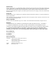
About Xantrex Xantrex Technology Inc. is a world-leading supplier of advanced power electronics and controls with products from 50 watt mobile units to one MW utility-scale systems for wind, solar, batteries, fuel cells, microturbines, and backup power applications in both grid-connected and stand-alone systems. Xantrex products include inverters, battery chargers, programmable power supplies, and variable speed drives that convert, supply, control, clean, and distribute electrical power.
About This Guide Purpose The purpose of this Owner’s Guide is to provide explanations and procedures for installing, operating, maintaining, and troubleshooting the Sine Wave Plus Long AC Conduit Box. Scope The Guide provides safety guidelines, and procedures for installing and operating the Sine Wave Plus Long AC Conduit Box. Audience The Guide is intended for a skilled electrician or technician who needs to install and operate the Sine Wave Plus Long AC Conduit Box.
About This Guide Conventions Used The following conventions are used in this guide. WARNING Warnings identify conditions that could result in personal injury or loss of life. CAUTION Cautions identify conditions or practices that could result in damage to the unit or other equipment. Important: These notes describe things which are important for you to know, but not as serious as a caution or warning.
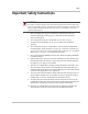
Safety Important Safety Instructions WARNING This chapter contains important safety and operating instructions for the Sine Wave Plus Long AC Conduit Box (ACCB-L and ACCB-L-L1) and the ACCB-L-L2 (ACCB-L2-PCK add-on package). Read and keep this Sine Wave Plus AC Conduit Box Long Owner’s Guide for future reference. 1. Before installing the Long AC Conduit Box, read all instructions and cautionary markings on the Long AC Conduit Box and all appropriate sections of this guide. 2.
Safety Explosive gas precautions 1. Working in the vicinity of lead-acid batteries is dangerous. Batteries generate explosive gases during normal operation. Therefore, you must read this guide and follow the instructions exactly before installing the Long AC Conduit Box. 2. To reduce the risk of battery explosion, follow these instructions and those published by the battery manufacturer and the manufacturer of the equipment in which the battery is installed.
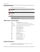
Contents Important Safety Instructions - - - - - - - - - - - - - - - - - - - - - - - - - - - - - - - - - - - - - - - - - - - -v 1 Introduction Introduction - - - - - - - - - - - - - - - - - - - - - - - - - - - - - - - - - - - - - - - - - - - - - - - - - - - - - - - - - - 1–2 Specifications - - - - - - - - - - - - - - - - - - - - - - - - - - - - - - - - - - - - - - - - - - - - - - - - - - - - - - - - - 1–4 AC Bypass Switch Assembly - - - - - - - - - - - - - - - - - - - - - - - - - - - - - - - - - - - - - - -
Contents 3 Operation The AC Bypass Switch - - - - - - - - - - - - - - - - - - - - - - - - - - - - - - - - - - - - - - - - - - - - - - - - - Operating the AC Bypass Switch - - - - - - - - - - - - - - - - - - - - - - - - - - - - - - - - - - - - - - - - - - Normal Operation - - - - - - - - - - - - - - - - - - - - - - - - - - - - - - - - - - - - - - - - - - - - - - - - - - Bypass Operation - - - - - - - - - - - - - - - - - - - - - - - - - - - - - - - - - - - - - - - - - - - - - - - - - - AC Input/Output Off -
Figures Figure 1-1 Figure 1-2 Figure 1-3 Figure 1-4 Figure 1-5 Figure 2-1 Figure 2-2 Figure 2-3 Figure 2-4 Figure 2-5 Figure 2-6 Figure 2-7 Figure 2-8 Figure 2-9 Figure 2-10 Figure 2-11 Figure 2-12 Figure 2-13 Figure 2-14 Figure 2-15 Figure 2-16 Figure 2-17 Figure 2-18 Figure 2-19 Figure 2-20 Figure 2-21 Figure 2-22 Figure 2-23 Figure 2-24 Figure 2-25 Figure 3-1 Figure 3-2 Figure 3-3 Figure 3-4 The Sine Wave Plus ACCB-L Basic- - - - - - - - - - - - - - - - - - - - - - - - - - - - - - - - - - - - 1–2 The Si
x
Tables Table 1-1 Table 2-1 Operational and Environmental Specifications for the ACCB-L, ACCB-L-L1, and ACCB-L-L2 - - - - - - - - - - - - - - - - - - - - - - - - - - - - - - - - - - - - - - - - - - - - - - - - - 1–4 Torque Values for Wiring- - - - - - - - - - - - - - - - - - - - - - - - - - - - - - - - - - - - - - - - - - 2–15 973-0031-01-01 Rev A xi
xii
1 Introduction Chapter 1, “Introduction” provides a basic introduction to the design and purpose of the Sine Wave Plus Long AC Conduit Box (ACCB-L). The following topics are covered in this chapter.
Introduction Introduction The Sine Wave Plus Long AC Conduit Box (ACCB-L and ACCB-L-L1) connects to the AC side of a Sine Wave Plus inverter and accepts AC conduit runs. It is designed to protect the wiring connections to the inverter and provides room for up to nine additional AC disconnect breakers (Square D, Type QOU, DIN rail mounted) to protect user-specified loads. There are three models of ACCB-L: • • • the ACCB-L Basic, the ACCB-L-L1, and the ACCB-L-L2.
Introduction ACCB-L-L1 ACCB-L-L2 L G N J I F M K E K H ACCB-L-L1 includes the components of the ACCB-L and adds the following: E ❐ One AC Bypass Switch Assembly (including wiring) F ❐ G ❐ H ❐ ❐I J ❐ AC Bus Bar (Neutral) AC Bus Bar (HOT L1) AC Input/output Terminal Block One length white NEUTRAL wire One length green GROUND wire ACCB-L-L2 is created by installing the ACCB-L2-PCK to the ACCB-L-L1.
Introduction Specifications The following table contains the specifications for the ACCB-L, the ACCB-L-L1, and the ACCB-L-L2. The ACCB-L-L2 is not available pre-built from the factory, but is created by field-installing an ACCB-L2-PCK into a ACCB-L-L1 model.
Specifications Table 1-1 Operational and Environmental Specifications for the ACCB-L, ACCB-L-L1, and ACCB-L-L2 ACCB-L ACCB-L-L1 ACCB-L-L2a Ratings 120/240 Vac/60 hz., splitphase, 60 Amp pass-thru 120/240 Vac/60 hz., splitphase, 60 Amp pass-thru 120/240 Vac/60 hz., splitphase, 60 Amp pass-thru Regulatory Certified by CSA to UL 1741- Certified by CSA to UL 17412001 (First Edition) and 2001 (First Edition) and CSA C22.2 No. 107.1-01 CSA C22.2 No. 107.
Introduction AC Bypass Switch Assembly The AC bypass switch assembly in the ACCB-L-L1 is designed for 120 Vac applications and comes with two 60-amp circuit breakers (one SPST and one DPST). The breaker pair is equipped with a lockout rocker that allows only one breaker to be ON at any given time. The AC bypass switch allows the generator or grid to provide power to the inverter loads in the event that the inverter is disabled for battery maintenance or removed for service.
Blockoff Plates Blockoff Plates Upper and Lower Blockoff Plates are included to enclose the open portions of the Long AC Conduit Box chassis. In the event that an inverter is removed for service, the Blockoff Plates secure the enclosure to prevent accidental contact with any AC power within the Long AC Conduit Box. Remove the Blockoff Plate (upper or lower) from its position for the inverter used in your installation. The Blockoff Plates will not be needed at all in a dual SW Plus inverter installation.
1–8
2 Installation Chapter 2, “Installation” provides installation and wiring instructions for the Sine Wave Plus Long AC Conduit Box. The following topics are covered in this chapter.
Installation Preparing for the Installation Important: Before installing the Long AC Conduit Box, read all instructions and cautionary markings located in this guide and in your inverter manual. Code Compliance Governing installation codes vary depending on the location and type of installation. Electrical installations must meet local and national wiring codes.
Configuration Planning Configuration Planning Wiring scenarios will depend upon the configuration of the overall system (i.e., Off Grid or On Grid, and output requirements). Pre-installation and mounting instructions apply to all configurations. Follow the instructions from page 2–4 to page 2–19 for all installations. After the pre-installation procedures have been completed, select the wiring scenario that applies to your configuration.
Installation Pre-Installation WARNING: Shock Hazard WARNING P N 3550 Ensure that no DC voltage is being supplied to the inverter and that no AC voltage is present on the AC wiring. Failure to do so could cause serious injury or death. A warning label is provided to inform all personnel that multiple sources of power are available inside. This label should be installed on the outside cover to be clearly visible. Ensure all sources are OFF or disconnected before servicing.
Pre-Installation Ventilation Requirements Minimum clearance for ventilation around the Long AC Conduit Box must be at least 12 inches (305 mm) at the top, the ends, and in front. This clearance is needed to prevent recirculating hot air from the inverter’s exhaust (DC side) from going back into the inverter’s intake (AC side). Please refer to the Sine Wave Plus Inverter/Charger Owner’s Guide for additional location considerations.
Installation Removing and Replacing the Cover Remove the top cover to install additional breakers and to connect the AC wiring of the Long AC Conduit Box to the Sine Wave Plus Inverter. Follow the diagram below to locate and remove, or replace, the appropriate screws and washers on the cover of the Long AC Conduit Box. Be sure to put the screws in a safe place when removed, so they don’t get lost. Torque to the values provided in Figure 2-3 when replacing them.
Pre-Installation Installing or Removing the Blockoff Plates The unit is shipped with both upper and lower blockoff plates installed. If you are installing a single-inverter system, remove the upper blockoff plate only. If you are installing a dual-inverter system, then remove the lower blockoff plate also. If a TX Autotransformer is to be installed in the lower position, remove the rectangular knockout in the lower blockoff plate. Do not remove the lower blockoff plate from that position.
Installation Knockout Preparation Knockout preparation should be done before mounting either the inverter or the Long AC Conduit Box. 1. Remove the appropriate knockouts from the AC side of the inverter for cabling from the Long AC Conduit Box terminal block to the inverter terminal block. See Figure 2-5 for the size and locations of the knockouts on the Sine Wave Plus Inverter Charger. 2.
Pre-Installation Outside wall of ACCB-L Base Inside wall of ACCB-L (closest to inverter) 3/4 and 1" Dual-Knockouts (x2) 3/4 and 1" Dual-Knockouts (x2) 2" Knockout 2" Knockout 3/4 and 1" Dual-Knockout (x4) Upper Blockoff Plate Front Cover Top Accessory Wiring Pass-thru slots (x2) 3/4" and 1" Dual-Knockouts (x6 ea) 2" Knockout (x1 ea) Rectangle knockouts for Square D Circuit Breakers (x12) Lower Blockoff Plate 2" Knockout (x1 ea) 1/2" Knockouts (x3 ea) 3/4" and 1" Dual-Knockouts (x6 ea) Accessory
Installation Installing Additional Breakers If additional AC circuit breakers are to be installed for specific AC loads or a generator disconnect, then install them per the manufacturer’s instructions on the DIN Rail in the space to the left of the factory-installed AC Bypass Breaker. The Long AC Conduit Box DIN Rail supports Square-D™, Type QOU, circuit breakers. To install additional Square-D™, Type QOU, circuit breakers in the Long AC Conduit Box: 1. Remove the top cover as described on page 2–6. 2.
Mounting Mounting The Long AC Conduit Box is designed to mount directly to the AC side of a Sine Wave Plus inverter. However, the SW Plus inverter can weigh up to 136 pounds (62 kg). The ACCB-L weighs up to 27 lbs (12.2 kg). Ensure the supporting surface is strong enough to hold twice the total weight being installed. Remember to include the weight of any other accessory, such as the DC Conduit Box, when considering the strength of the supporting surface.
Installation 3. Lift the inverter and place the mounting holes in the rail directly over the mounting hooks on the panel and lower into place. 4. Install four ¼-20 phillips screws provided with the panel, into the mounting holes of the Long AC Conduit Box, but do not fully tighten. 5. Lift the second inverter (if used) and place the mounting holes in the rail directly over the mounting hooks on the panel and lower into place. 6.
Mounting Mounting on Plywood Important: Ensure that the factory-installed cables in the Long AC Conduit Box are not pinched, crushed, removed, or damaged during the installation to the inverter. To mount the Long AC Conduit Box on plywood: 1. With the help of another person, lift the inverter and mount it into place. Secure it to the plywood with #10 wood screws (14 total - length to penetrate 1½ inches or more into the studs.
Installation Wiring - General The ACCB-L comes with a ground bar only. The ACCB-L-L1 is pre-wired at the factory and ready for connection to one Sine Wave Plus Inverter/Charger. The factory-installed wires are labeled to assist with the installation procedure. See Figure 2-12 on page 2–17 for an illustration of the ACCB-L-L1. See Figure 2-13 on page 2–18 for an illustration of the ACCB-L2-PCK installed in the ACCB-L-L1 to create the ACCB-L-L2.
Wiring - General Wire Sizes and Disconnect Requirements The AC Input/Output Terminal block in the ACCB-L-L1 accept wires sized #2/0 to 14 AWG. The ground bar in both models has nine holes and accepts #4 to 14 AWG wires. The AC Bus Bar (for neutral and hot connections) has dual sizes. The smaller nine holes accept #6 to 14 AWG wire and the larger two holes accept #1/0 to 14 AWG. Determine the wire sizes and disconnect sizes required for the installation. See Table 2-1 for torque values.
Installation IMPORTANT: Always use approved wiring per NEC/CEC. AC Bus Bar (for L1 HOT) Xantrex P/N: • ACBUSBAR) Includes two 10x32 phillips screws and nuts, the bus bar and plastic stand-offs to isolate it from the chassis. Can be used for HOT (L1 or L2), and/or neutral connections. Torque to 31 in-lb when installing.
Wiring - General AC Bus Bar (L1 HOT) GROUND Wire - Connects to the SW Plus Inverter GROUND Bar Ground Bar AC Bus Bar (Neutral) NEUTRAL Wire - Connects to the SW Plus Inverter NEU1 terminal HOT OUT Wire - Connects to the SW Plus Inverter INV OUT terminal AC Bypass Switch Assembly HOT IN Wire - Connects to the SW Plus Inverter AC1 GRID or AC2 GEN terminal DIN Rail (part of chassis - all models) DIN Rail End Clamp AC Input/Output Terminals Figure 2-12 ACCB-L-L1 Internal Components (Factory installed)
Installation Optional Field-installed, AC Bus Bar (L2 HOT) Factory-installed GROUND Wire - Connects to the SW Plus Inverter #1 GROUND Bar Field-installed GROUND Wire - Connects to the SW Plus Inverter #2 GROUND bar* Factory-installed NEUTRAL Wire - Connects to the SW Plus Inverter #1 NEU1 terminal Field-installed NEUTRAL Wire - Connects to SW Plus Inverter #2 NEU1 terminal* Factory-installed HOT IN Wire - Connects to the SW Plus Inverter #1 INV OUT terminal Factory-installed HOT OUT Wire - Connects to t
Wiring for Off-Grid Applications Wiring for Off-Grid Applications The following illustrations show the wiring examples for six basic off-grid configurations using the ACCB-L-L1 with a minimum number of breakers installed for clarity. For other possible configurations, consult a qualified electrician or a Xantrex certified dealer. (See www.xantrexREdealer.com).
Installation The following illustration shows the complete wiring for the ACCB-L-L1 and SW Plus Inverter in an off-grid configuration. This illustration includes the use of field-installed circuit breakers in the ACCB-L-L1 for AC distribution, instead of using a separate sub panel. *IMPORTANT: To use both legs of a 120/240 Vac generator in a single-inverter configuration, a Step-Down Autotransformer should be installed.
Wiring for Off-Grid Applications Step-down Configurations (240 Vac to 120 Vac) The following illustration shows the complete wiring for the ACCB-L-L1, TX Autotransformer, and a SW Plus Inverter for a Step-down Configuration to use a 240 Vac-Only Generator.
Installation The following illustration shows the complete wiring for the ACCB-L-L1, TX Autotransformer, and a SW Plus Inverter for a Step-down Configuration to use a 240 Vac-Only Generator. This configuration uses the ACCB-L-L1 as the sub panel. Note: Because there is only one circuit breaker installed (other than the AC Bypass Switch), the output for the ACCB-L doesn’t not need to be connected to the L1 HOT Bus Bar. It can be connected to the line side of the field-installed circuit breaker.
Wiring for Off-Grid Applications Step-up Configuration (Deep Well Pump) (120 Vac to 240 Vac) The following illustration shows the complete wiring for the ACCB-L-L1, TX Autotransformer, and a SW Plus Inverter for a Step-up Configuration to provide power for a 240 Vac Load.
Installation Dual Inverter Configurations (120 Vac and 240 Vac) The following illustration shows the complete wiring for the ACCB-L-L2 (ACCB-L-L1 with ACCB-L2-PCK installed) and dual SW Plus Inverters in an off-grid application. In this configuration, the generator’s output (L1 and L2) is connected to the AC Bypass breakers, then to the SW Plus input and output.
Wiring for On-Grid Applications Wiring for On-Grid Applications The following illustrations show the complete wiring to the six basic on-grid configurations. For other possible configurations, consult a qualified electrician or a Xantrex certified dealer (See www.xantrexREdealer.com). Single Inverter Configurations (120 Vac) The following illustration shows the complete wiring for the ACCB-L-L1 and SW Plus Inverter in an on-grid configuration.
Installation The following illustration shows the complete wiring for the ACCB-L-L1 and SW Plus Inverter in an on-grid configuration. This diagram includes the use of a generator disconnect breaker and load breakers in the ACCB-L-L1. *IMPORTANT: To use both legs of a 120/240 Vac generator in a singleinverter configuration, a Step-Down Autotransformer should be installed. See Figure 2-16 or Figure 2-17 for wiring a Step-Down Application depending on your specific installation.
Wiring for On-Grid Applications Step-up Configurations (Utility Backup) (120 Vac to 240 Vac) The following illustration shows the complete wiring for the ACCB-L-L1, TX Autotransformer, and a SW Plus Inverter for a Step-up Configuration to provide power for a 240 Vac Load.
Installation Dual Inverter Configurations (120 Vac and 240 Vac) The following illustration shows the complete wiring for the ACCB-L-L2 (ACCB-L-L1 with ACCB-L2-PCKinstalled) and dual SW Plus Inverters in an ongrid application. In this configuration, the utility grid is connected to the AC Bypass Breakers, then to the SW Plus input and output.
Additional Accessory Wiring Additional Accessory Wiring If you have any of the following accessories connected (or to be connected) to your inverter, then you will also need to pass their connecting cables through the Long AC Conduit Box to the AC side of the inverter: • • • • • Generator Start Module (GSM) for automatic generator control Auxiliary Load Module (ALM) for controlling auxiliary loads such as alarms or ventilator fans Emergency Power Off (EPO) switch (not supplied by Xantrex) Inverter Control
Installation See "IMPORTANT" note in Figure 2-24.
3 Operation Chapter 3, “Operation” describes the different modes and operation of the AC Bypass Switch(es) on the ACCB-L-L1, or for the second AC Bypass Switch (ACCB-L-L2) if installed. The following topics are covered in this chapter.
Operation The AC Bypass Switch During normal operation (Figure 3-2 on page 3–3), AC power passes from the single external AC source (generator or grid) through the inverter to the AC loads. The inverter monitors the incoming power and uses this power to keep the batteries charged. When this external source of AC power is not available, the inverter switches to external DC power (e.g., batteries, generator, solar, wind, hydro) and continues to power the load.
Operating the AC Bypass Switch Normal Operation External AC power passes to the AC Bypass Switch through the inverter to power the load (Figure 3-2). In this configuration, power passes from the inverter, through the AC Bypass Switch, to the connected load. When external AC power is not available, power from the external DC source is used by the inverter to power the AC loads.
Operation AC Input/Output Off No power to the load or inverter (Figure 3-4). In this configuration, power from both the external sources of AC and the inverter is removed from the loads. This allows the inverter that is connected to the AC Bypass breaker to be removed for service.
Warranty and Return Information Warranty What does this warranty cover? This Limited Warranty is provided by Xantrex Technology, Inc. ("Xantrex") and covers defects in workmanship and materials in your Sine Wave Plus Long AC Conduit Box. This warranty period lasts for two (2) years from the date of purchase at the point of sale to you, the original end user customer. You require proof of purchase to make warranty claims.
Warranty and Return What does this warranty not cover? This Limited Warranty does not cover normal wear and tear of the product or costs related to the removal, installation, or troubleshooting of the customer's electrical systems.
Warranty and Return Return Material Authorization Policy Before returning a product directly to Xantrex you must obtain a Return Material Authorization (RMA) number and the correct factory "Ship To" address. Products must also be shipped prepaid. Product shipments will be refused and returned at your expense if they are unauthorized, returned without an RMA number clearly marked on the outside of the shipping box, if they are shipped collect, or if they are shipped to the wrong location.
Warranty and Return Information About Your System As soon as you open your Sine Wave Plus Long AC Conduit Box package, record the following information and be sure to keep your proof of purchase. ❐ Serial Number _________________________________ ❐ Purchased From _________________________________ ❐ Purchase Date _________________________________ If you need to contact Customer Service, please record the following details before calling.
Index A abbreviations and acronyms iv AC Bypass Switch Assembly 1–6 AC conduit box - Long (ACCB-L) introduction 1–2 specifications 1–4 AC disconnect breakers 1–2 AC load breakers 2–10 additional accessory wiring 2–29 additional breakers in the ACCB-L 2–10 Auxiliary Load Module (ALM), wiring for 2–29 B Blockoff Plates (BP-1) 1–7 breakers 1–4 owner-installed 2–10 bypass switch 1–6 AC output OFF 3–4 bypass operation 3–3 C inverter purchase date WA–4 serial number WA–4 Inverter Communications Adapter (ICA) 2
Index T tools required for installation 2–2 V Ventilation Requirements 2–5 W warranty out of warranty service WA–3 terms and conditions WA–1 wiring additional accessories 2–29 X Xantrex web site iv IX–2 973-0031-01-01 Rev A
Xantrex Technology Inc. 1 800 670 0707 Tel toll free NA 1 360 925 5097 Tel direct 1 800 994 7828 Fax toll free NA 1 360 925 5143 Fax direct customerservice@xantrex.com www.xantrex.