
Conduit Box Owner's Guide ACCB-L, ACCB-L-L1


973-0031-01-01 Rev A ix
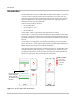
Figure 1-1 The Sine Wave Plus ACCB-L Basic- - - - - - - - - - - - - - - - - - - - - - - - - - - - - - - - - - - - 1–2
Figure 1-2 The Sine Wave Plus Long AC Conduit Box (ACCB-L-L1, and ACCB-L-L2)- - - - - - - - 1–3
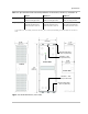
Figure 1-3 ACCB-L Dimensions (not to scale) - - - - - - - - - - - - - - - - - - - - - - - - - - - - - - - - - - - - 1–5
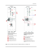
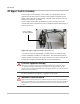
Figure 1-4 Bypass Switch Assembly in the ACCB-L-L1- - - - - - - - - - - - - - - - - - - - - - - - - - - - - - 1–6
Figure 1-5 Blockoff Plates - - - - - - - - - - - - - - - - - - - - - - - - - - - - - - - - - - - - - - - - - - - - - - - - - - 1–7
Figure 2-1 Shock Hazard Warning Label - - - - - - - - - - - - - - - - - - - - - - - - - - - - - - - - - - - - - - - - 2–4
Figure 2-2 Clearance Requirements for Ventilation - - - - - - - - - - - - - - - - - - - - - - - - - - - - - - - - - 2–5
Figure 2-3 Cover Removal and Replacement - - - - - - - - - - - - - - - - - - - - - - - - - - - - - - - - - - - - - 2–6
Figure 2-4 The Blockoff Plate on the Long AC Conduit Box- - - - - - - - - - - - - - - - - - - - - - - - - - - 2–7
Figure 2-5 SW Plus Inverter, AC Side Showing Knockout Location - - - - - - - - - - - - - - - - - - - - - - 2–8
Figure 2-6 Knockouts Locations - - - - - - - - - - - - - - - - - - - - - - - - - - - - - - - - - - - - - - - - - - - - - - 2–9
Figure 2-7 Installing Additional Breakers on the DIN Rail - - - - - - - - - - - - - - - - - - - - - - - - - - - 2–10
Figure 2-8 The Xantrex Back Plate - - - - - - - - - - - - - - - - - - - - - - - - - - - - - - - - - - - - - - - - - - - 2–11
Figure 2-9 Installing the ACCB-L on the Backplate - - - - - - - - - - - - - - - - - - - - - - - - - - - - - - - - 2–12
Figure 2-10 Installing the ACCB-L to the SW Plus Inverter on Plywood- - - - - - - - - - - - - - - - - - - 2–13
Figure 2-11 ACCB-L Approved Internal Components - - - - - - - - - - - - - - - - - - - - - - - - - - - - - - - 2–16
Figure 2-12 ACCB-L-L1 Internal Components (Factory installed) - - - - - - - - - - - - - - - - - - - - - - - 2–17
Figure 2-13 ACCB-L-L1 Internal Components with the Optional ACCB-L2-PKG Installed - - - - - 2–18
Figure 2-14 Wiring an Off-grid Application Using a Single Inverter - - - - - - - - - - - - - - - - - - - - - 2–19
Figure 2-15 Wiring an Off-grid Application Using a Single Inverter (No Sub Panel) - - - - - - - - - - 2–20
Figure 2-16 Wiring an Off-grid Application Using a Single Inverter and TX Autotransformer
in a Step-Down Configuration- - - - - - - - - - - - - - - - - - - - - - - - - - - - - - - - - - - - - - - 2–21
Figure 2-17 Wiring an Off-grid Application Using a Single Inverter and TX Autotransformer
for a Step-Down Configuration (No Sub Panel) - - - - - - - - - - - - - - - - - - - - - - - - - - - 2–22
Figure 2-18 Wiring an Off-grid Application Using a Single Inverter and TX Autotransformer
for a Step-Up Configuration for a Deep Well Pump Application- - - - - - - - - - - - - - - - 2–23
Figure 2-19 Wiring an Off-grid Application Using Dual Inverters (ACCB-L-L2) - - - - - - - - - - - - - 2–24
Figure 2-20 Wiring an On-grid Application Using a Single Inverter - - - - - - - - - - - - - - - - - - - - - - 2–25
Figure 2-21 Wiring an On-grid Application Using a Single Inverter (No Sub Panel) - - - - - - - - - - - 2–26
Figure 2-22 Wiring an On-grid Application Using a Single Inverter and TX Autotransformer
for a Step-Up Configuration for Utility Backup - - - - - - - - - - - - - - - - - - - - - - - - - - - 2–27
Figure 2-23 Wiring an On-grid Application Using Dual Inverters (ACCB-L-L2) - - - - - - - - - - - - - 2–28
Figure 2-24 Accessory Wiring for Single-Inverter Configurations - - - - - - - - - - - - - - - - - - - - - - - 2–29
Figure 2-25 Accessory Wiring for Dual-Inverter Configurations - - - - - - - - - - - - - - - - - - - - - - - - 2–30
Figure 3-1 AC Bypass Switch Mode Summary - - - - - - - - - - - - - - - - - - - - - - - - - - - - - - - - - - - - 3–2
Figure 3-2 Normal Operation - - - - - - - - - - - - - - - - - - - - - - - - - - - - - - - - - - - - - - - - - - - - - - - - 3–3
Figure 3-3 Bypass Operation - - - - - - - - - - - - - - - - - - - - - - - - - - - - - - - - - - - - - - - - - - - - - - - - 3–3
Figure 3-4 AC Output OFF - - - - - - - - - - - - - - - - - - - - - - - - - - - - - - - - - - - - - - - - - - - - - - - - - 3–4
Figures