
- Xantrex Sine Wave Plus AC Conduit Box (ACCB) Owner's Guide Owner's Guide


Installation
1–30 975-0046-01-01
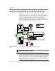
Wiring for On-Grid Applications Using an AC Distribution
Panel and an Internal Generator Disconnect Breaker
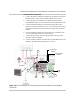
The following diagram shows the complete wiring diagram for wiring the
ACCB and Sine Wave Plus Inverter inputs and outputs in an on-grid
application using an AC distribution panel for the outputs and a 120 Vac
generator for input. This diagram also uses an internal generator
disconnect breaker in the ACCB. Wiring instructions are provided for
making ground connections first (page 1–31), neutral connections second
(page 1–32), and hot connections last (page 1–33).
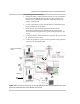
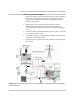
Figure 1-26
Wiring an On-grid Application USING an AC Distribution Panel
WARNING: Shock Hazard
Ensure that all AC and DC power is not “live” before proceeding.
Important:
The inverter bypass circuit breaker can only be wired directly to,
and work with, a single AC source. In a system that has multiple AC sources, you
must decide which AC source will be wired through the inverter bypass circuit
breaker and which will not. The following illustrations assume that the primary
AC input source will be the utility grid.
120/240V AC Panel
L1 L2
NE UTRAL
GROU ND
Set Inverter
OFF SRCH ON CHG
Sine Wa ve Plus Inv erter / Charg er
INV O UT
NE U O UT
NE U 2
NE U 1
AC1 GR ID
AC2 GE N
AC TERMINAL
BLO C K
HOT
NEUTRAL
GROUND
AC Dist ributi on Panel
(120 Vac Only)
To Pr imary
System
Ground
Neutral to
Ground
Bond
120V AC Generator
HOT NEU GND
DD
AC
IN
AC
OUT
NEU
D
AC Load
Ground
Neutral
HOT (Owner supplied)
LEGEND
HOT (Factory installed)