
Multifunction DC Controller C35, C40, C60
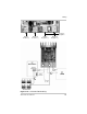

Wiring
975-0004-01-02 Rev D 41
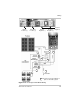
controller are strongly recommended. Put a surge protection
device on the input line of the C-Series controller between
the PV array and the controller.
If the battery, is over 15 feet away from the controller, or if it
is routed next to other wiring or sources of power, additional
surge protection devices are recommended. Put the surge
protection device for this scenario on the battery input line
between the battery and the controller.
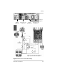
Over-current Protection
The NEC requires conductors and over-current devices be
operated at no more than 80% of their rating. Refer to Table
2-3 for a listing of the minimum wire size and over-current
device ratings to be used for each model.
As a minimum, a 60-amp DC-rated current-limiting fuse or
circuit breaker should be installed near the battery for
protection from short circuits. To meet NEC requirements,
use a 60 amp circuit breaker listed for 100% duty for the C60.
To meet UL requirements, use #6 AWG copper wires rated
for 90 °C (194 °F) for the C60. Over-current protection for
the battery circuit is to be provided by others. Refer to
Table 2-3 for the correct ratings of the fuse and circuit
breaker.
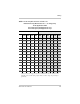
Table 2-3
Minimum Wire Size
Controller Minimum Wire Size Over-Current Device Rating
C35 #8 AWG 45 amps
C40 #8 AWG 50 amps
C60
a
a.To meet UL requirements, use #6 AWG, (90 °C/194 °F) wire and a 60 amp Listed 100%
duty over-current device for the C60 controller.
#6 AWG (90 °C/194 °F wire) 60 amps (listed 100% duty)
C60
#4 AWG
b
(75 °C/167 °F wire)
b.Not approved by UL for direct connection into the controller. Use a splicer block and #6
AWG (90 °C/194 °F) wire to connect to the controller terminals.
60 amps (listed 100% duty)