I4.
TABLE OF CONTENTS One Page Summary of Features Introduction and Special Notes Monitor Functions Inverter and Charger Functions Status Line and Starting and Stopping Equalize Setup Inverter Setup Monitor Setup Functions Setup Data Mode How to Use The Link 2000 Control Panel Ideal Charge Curve Synchronizing to a Full Battery (Resetting Amp Hours to Zero) Rules for Changing the Charged Parameters Selection Rules Reset / Info Functions High Discharge Rates and Peukert's Equation Typical Peukert's Exponents Erro
INTRODUCTION AND SPECIAL NOTES The LINK 2000 is an integrated battery monitor and inverter/charger control. It displays the critical information necessary for 12 V or 24 VDC system battery management and allows precise control of critical inverter and charger features. The Link 2000-R comes with an additional manual describing the Ideal Regulator option.
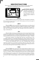
MONITOR FUNCTIONS Please also refer to the one-page summary of features in center of this manual. The small blue legends indicate Setup functions described later. BATTERY SELECT The battery to be monitored is selected by pressing the #1 or #2 switch. A Green LED indicates which battery is selected. ("Battery" may be a "bank" of batteries.) VOLTS When the VOLTS switch is pressed, the voltage of the selected battery is displayed. The measurement range is from 8.5 V to 50 V. The resolution is 0.05 volts.
Time remaining display reads C C C. For the TIME function to operate correctly you must enter your BATTERY CAPACITY through the SETUP routine (see page 9). You must also set up the correct PEUKERT'S EXPONENT (see page 13). It is also affected by your selection of DISCHARGE FLOOR (see page 14). Caution: The TIME display is an estimate of how long your battery can sustain a load.
STATUS LINE There are four LED status indicators to show the presence of AC power and the charger's cycle state. AC IN: CHARGE: ACCEPT: FLOAT: Green LED on when AC is present. Red LED on when charger is in Charge mode. Flashes Red when charger is in Equalize mode. Orange LED on when charger is in Acceptance mode. Green LED on when charger is in Float mode.
SETUP I4.35 The LINK 2000 has been set up with default values chosen to work with a typical system. Normally the only values that must be changed are: 1) Battery capacity (page 9) 3) Battery type (liquid or gel) (F02 page 11). 2) Ambient Temperature (F03 page 11) 4) Peukert's exponent (F08 page 13). The SETUP BUTTON is used to access the functions in small blue text below each button's primary function. It is also used for certain advanced functions described later.
INVERTER SETUP IDLE MODE: The default value is 4 watts. This means it takes a 4-watt AC load to turn the inverter on from its low power idle mode. Setting a value of 0 watts means the inverter is always on. The low power idle current is about 0.25 amps. When idle mode is set to 0 W the current consumption goes up to about 0.9 amps. Range = 0 W, 4 W, 6 W, 15 W. (0–15 watts in 5-watt steps in Series 458 units.
MONITOR SETUP Normally the only MONITOR SETUP parameter that must be changed is BATT CAP (see bottom of this page). Please read the section on selecting charged parameters (page 21–22) before changing CHARGED V or CHARGED % default values. (See FUNC SETUP on page 10 for other system values that may need to be changed.
FUNCTIONS SETUP FUNC: The FUNC (Function) mode is used to set up special functions or features that are not commonly changed. They might be thought of as internal software switches that allow the selection of special functions, or values that, once set, are seldom changed. Normally the only functions that must be changed are F02 Battery Type, F03 Ambient Battery Temperature, and F08 Peukert's Exponent. (See page 9 for how to set battery capacity.
F02 - BATTERY TYPE 0 = LIQUID CELL (DEFAULT) 1 = GEL CELL (STANDARD) 2 = GEL CELL (FAST CHARGE) 3 = AGM (Absorbed Glass Mat) This function (Default: Type 0, standard liquid cells) sets the appropriate charge and float voltages for the FREEDOM charger (see table below) and sets an appropriate Peukert exponent. Gel cell owners may use Type 1 or Type 2, but should consult with the battery manufacturer prior to using the more aggressive charging regimen described by Type 2.
Freedom units produced prior to serial #100,000 have temperature compensation only for warm or cool environments. The temperature setup sets the voltages as per below: TEMP Above 80 °F Below 80 °F TYPE 0 (Liquid) Accept Float Equalize 13.9 13.3 15.8 14.4 13.5 16.3 TYPE 1 (Gel 1) Accept Float Equalize 14.1 13.8 14.1 14.4 13.8 14.
F08 - SET PEUKERT'S EXPONENT DEFAULT = 1.25 RANGE = 1.00–1.50 STEP = 0.01 Sets the exponent for Peukert’s equation. A setting of 1.00 defeats Peukert's calculation. See pages 24–27 for a discussion of Peukert's equation and typical values for various batteries. Properly setting Peukert's exponent ensures a more accurate display of time remaining and percent remaining.
F13 SET DISCHARGE FLOOR DEFAULT = 100% RANGE = 50%–100% STEP = 5% When this option is activated, you may set a discharge floor for each battery bank. When the discharge floor is set to 50%, the Time Remaining display reports time remaining until the battery reaches the 50% discharged level. You may set the discharge floor from 50% to 100% in 5% increments. When the Settable Discharge Floor is 100%, time remaining to 100% discharge is displayed. You may set a discharge floor for each battery.
DATA MODE DATA: The DATA mode is used to recall key historical information about the battery (battery banks). To access the DATA mode: 1) Select Battery #1 or #2 to review its data. 2) Press and hold the SETUP button until the green LED begins to flash then release the button. 3) Now press the (blue) DATA button. Each time you press the DATA button a new piece of data is displayed.
HOW TO USE THE LINK CONTROL PANEL BATTERY MANAGEMENT PHILOSOPHY: Recharge When the Battery is 50% Discharged! The LINK 2000 is a guide to the battery's state of charge. Our Mid-Capacity Rule says you should begin charging when your LINK 2000 shows that 50% of battery capacity has been consumed. In Marine and RV systems, which are trying to minimize charging time with an engine driven alternator or generator driven charger, the battery is normally charged only to the 85% level.
parameters. The battery will be gassing and you will see an accumulation of a large number of amp hours each day. This is a clear indication that you are destroying your battery by overcharging. Check your LINK 2000 before turning off a charging source to see that you have not accumulated too many overcharge amp hours. When discharging begins, overcharge amp hours are erased and the LINK 2000 resets to zero.
IDEAL CHARGE CURVE The LINK 2000 transmits critical battery state of charge information to the FREEDOM Inverter/Charger. This enables the charger to conform to our proven Ideal Charge Curve with four basic cycles: Charge, Accept, Float, and Equalize. The CHARGE cycle supplies full charger output current until the battery reaches the Accept charging voltage (14.4 V typically). The ACCEPT cycle continues until the battery is accepting only a small amount of current. The battery is now full.
HOW TO TELL WHEN A BATTERY IS FULLY CHARGED (CHARGED BATTERY PARAMETERS) MULTIPLE STAGE CHARGING SYSTEMS If you are using the charger in the FREEDOM, the battery is charged when the system switches to the Float cycle. If another manufacturer's charging system is being used it should be adjusted so the transition from Acceptance Charging to Float will occur when the charging current, at the Acceptance Voltage (14.4/28.8 V typically), drops to below 2% of the battery capacity.
SYNCHRONIZING YOUR LINK 2000 TO A CHARGED BATTERY A charged battery has zero Ahrs removed. Synchronizing your LINK 2000 to read zero when the battery is charged ensures that you always know the net number of amp hours removed. The charged parameters on the previous page indicate when a charging system has put as much energy into a battery as it normally can and the battery can be considered charged.
MANUALLY SELECTING THE CHARGED BATTERY PARAMETERS DISCUSSION: HOW THE LINK 2000 USES THESE VALUES The LINK 2000 allows the setup of specific charged parameters. The factory default values have been carefully chosen to work on most systems, including constant voltage and multiple step charging systems. The factory Charged Parameters are 13.2 volts and 4 amps (2% of the default battery capacity of 200 Ah). This means when the battery is above 13.
Feature Summary of LINK 2000 Integrated Battery Monitoring & Inverter/Charger Control Control Functions Battery Display Select Green LED indicates selection. Press to select BATTERY #1. Green LED indicates on. INVERTER may be turned On or Off independently from charger. RESET A hrs of the selected battery to zero. Press to select BATTERY #2. IDLE MODE sets the load sensitivity while idling, expressed in Watts. Range depends on Freedom inventer being used. DATA Displays historical data about battery.
RULES FOR CHANGING THE CHARGED BATTERY PARAMETERS If you must change the Charged Parameters please use the following rules. 1) The Charged Voltage MUST be at least 0.1 V BELOW the charging system voltage. 2) The Charged Current % times declared Battery Capacity MUST be GREATER than the minimum current the charging system maintains the battery at, or turns off at. If the charged parameters are not correctly selected, the LINK 2000 will never recalculate the CEF.
RESET / INFO FUNCTIONS The drawing below shows the Reset/Info Functions layout. To access these, press the SETUP BUTTON for ten seconds. The time is long to avoid unintentionally entering this mode. When the green LED begins to flash quickly (about three times per second) select the Advanced Function you wish by consulting this drawing. The display returns to the monitoring mode five seconds after the selected function button is released.
HIGH DISCHARGE RATES & PEUKERT'S EQUATION Peukert's Equation describes the effect of different discharge rates on battery capacity. As the discharge rate increases the available battery capacity decreases. The tables on pages 25, 26 and 27 have typical values of "n" for common batteries. Page 25 is a look-up table, pages 26 & 27 have "n" values for common batteries, and page 27 has the formula for calculating "n" for other batteries.
TABLE OF PEUKERT'S EXPONENT FOR VARIOUS BATTERY RATINGS DIRECTIONS: FIND THE 20-HOUR RATING OF YOUR BATTERY ON THE HORIZONTAL AXIS. FIND THE RESERVE CAPACITY RATING ON THE VERTICAL AXIS. THE INTERSECTION IN THE TABLE GIVES THE "N" VALUE. 20 Hr rating Reserve Minutes 60 90 120 130 150 160 180 190 210 230 240 270 300 330 350 360 375 390 395 420 450 60 70 85 86 1.41 1.22 1.32 1.46 1.47 1.09 1.17 1.30 1.31 1.05 1.13 1.25 1.26 1.06 1.17 1.18 1.02 1.14 1.14 1.07 1.08 1.04 1.05 90 95 105 108 112 1.
TYPICAL PEUKERT'S EXPONENTS The following table contains values for the exponent "n" for various batteries and manufacturers. They are calculated from the 20-hour rating and the Reserve Minutes @ 25 A as supplied by the manufacturer. Page 27 shows how the calculation is performed. You may choose a battery of similar size and construction as a guide in selecting "n" if your battery does not appear in this table, or you may calculate "n" as shown.
TYPICAL PEUKERT'S EXPONENTS Surrette and Rolls Batteries Model Volts Res. Min. 20-Hr. Rating EHG-208 6 345 208 EIG-225 6 350 225 EIG-262 6 395 262 24/90 12 165 90 27/12M 12 190 112 30H/108 12 230 108 HT/4D 12 348 170 HT/8D 12 450 221 *Use Max allowed "n" of 1.50 "n" 1.42 1.54* 1.72* 1.16 1.23 1.08 1.15 1.20 CALCULATING PEUKERT'S EXPONENT Example of using Reserve Minutes @ 25 amps and the 20-hour rate to calculate "n".
ERROR CODES AND TROUBLESHOOTING The following error codes are displayed when the LINK 2000 detects a problem. The display alternates between the selected monitoring function and the Error Code. The Error Code continues to flash until the error is corrected. (Error codes are the same for all models.) CODE E-1 DEFINITION INVERTER HIGH DC/BATTERY VOLTAGE SHUTDOWN: Battery voltage has risen above 15.5 V for 12 V models or above 31 V for 24 V models. Check all charging sources.
E-10 LINK 2000 DEPOWERED: Displayed on power up and when power has been interrupted or dipped below the operating voltage of the LINK 2000. May be caused by voltage dips during engine starting if the meter is powered by a starting battery. E-11 NOT USED: E-12 BATTERY #1 VOLTAGE SENSE LEADS OPEN: Check the fuse and connections in the sense lead (Blue wire) to battery #1. E-13 BATTERY #2 VOLTAGE SENSE LEADS OPEN: Check the fuse and connections in the sense lead (Violet wire) to battery #2.
MICROPROCESSOR RESET PROCEDURE The LINK 2000 uses a microprocessor to perform all of its calculations and functions. We have worked very hard to ensure a stable, trouble-free product. However, like all computer products, the unit is sometimes susceptible to power supply dips or surges that can cause erratic behavior or memory errors.
RESETTING MEMORY TO FACTORY VALUES: If some portions of the memory have been "corrupted" you should consider resetting to the factory default values and then changing any specific values you need to. This ensures a "clean slate" for your new setup. 1) Follow the procedure outlined on the previous page to first reset the microprocessor. 2) Select Battery bank #1 on the LINK 2000 to reset to factory values for Battery #1.
SETUP AND HISTORICAL DATA SUMMARY The following table is a summary of the values that may be changed through setup or by accumulating historical data. The column on the right is provided to write down your setup values or historical data. Be sure and know these values before calling for customer service. Multiply voltage values by two for 24-volt systems. PARAMETER DEFAULT VALUE SETUP VALUE B1 VCHARGED B2 VCHARGED B1 AMPSCHARGED 13.2 (13.5 IF F05 IS ON) 13.2 (13.
WARRANTY What does this warranty cover? This Limited Warranty is provided by Xantrex Technology, Inc. (“Xantrex”) and covers defects in workmanship and materials in your Xantrex Link 2000 Inverter Controller and Dual Battery Monitor. This warranty lasts for a Warranty Period of 12 months from the date of purchase at point of sale to you, the original end user customer. This Limited Warranty is transferable to subsequent owners but only for the unexpired portion of the Warranty Period.
Disclaimer Product THIS LIMITED WARRANTY IS THE SOLE AND EXCLUSIVE WARRANTY PROVIDED BY XANTREX IN CONNECTION WITH YOUR XANTREX PRODUCT AND IS, WHERE PERMITTED BY LAW, IN LIEU OF ALL OTHER WARRANTIES, CONDITIONS, GUARANTEES, REPRESENTATIONS, OBLIGATIONS AND LIABILITIES, EXPRESS OR IMPLIED, STATUTORY OR OTHERWISE IN CONNECTION WITH THE PRODUCT, HOWEVER ARISING (WHETHER BY CONTRACT, TORT, NEGLIGENCE, PRINCIPLES OF MANUFACTURER’S LIABILITY, OPERATION OF LAW, CONDUCT, STATEMENT OR OTHERWISE), INCLUDING WITHOUT
Return Procedure 1. Package the unit safely, preferably using the original box and packing materials. Please ensure that your product is shipped fully insured in the original packaging or equivalent. This warranty will not apply where the product is damaged due to improper packaging. 2. • • • • Include the following: The RMA number supplied by Xantrex Technology Inc clearly marked on the outside of the box. A return address where the unit can be shipped. Post office boxes are not acceptable.
REQUIRED READING Before wiring the LINK 2000, install the shunt as indicated. All wiring should be done before installing the fuses. GENERAL NOTES 1) Wiring to the LINK 2000 should be #16 or #18 AWG. (Larger wire is acceptable, but not necessary.) Wiring should be per NEC or applicable standards. 2) The Shunt Sense Leads should be a twisted pair. Leads up to 1,000 feet long may be used if they are not run along with other noise-producing conductors. Offset error should be less than 0.2 amps.
remember that instrumentation and other loads grounded directly to the engine block will not be measured unless their negatives are relocated to the load side of the Battery Shunt. Special high current shunts are also a solution and may be ordered from us. A separate engine starting battery whose negative is connected directly to the engine also solves the problem. 6) We have shown several wires connected to the load side of the battery shunt in the wiring diagram.
The VIOLET WIRE (B2 V) supplies Battery #2 voltage for sensing. It should be supplied directly from Battery #2. Be sure to install the 2-amp fuse shown in the drawing. NOTE: If only one battery is to be monitored, connect the VIOLET wire to the BLUE wire. The GREEN WIRE (B1SHG) is connected to the SMALL SCREW ON THE GROUND SIDE, OR LOAD SIDE, of the battery #1 shunt (B1SHG). This wire must be located exactly as described to ensure accuracy of current measurements.
SPECIFICATIONS Power to Link 2000 Power Supply Voltage Power Supply Current Measurements Voltage Range Voltage Resolution Voltage Accuracy Current Range Current Resolution Current Accuracy Current Shunt Amp Hour Range Amp Hour Accuracy Time Remaining Range Charger Voltage Regulation Cut out size: Panel size: Weight: 9–40 volts DC (not for use with 32 V systems) 28 mA (typical; backlight adds 1 to 18 mA ) 8.5–50 volts DC 0.05 volts DC + 0.10 volts DC at full scale. + 500 amps DC 0.1 amp DC (from 0 to + 42.
40 LINK 2000 USED AS A BATTERY/SOURCE MONITOR WITH A PHOTOVOLTAIC CHARGING SYSTEM Notes: 1) Shunt rated at 500 Amps max. 2) Link 2000 meter #18 AWG minimum. Shunt leads are twisted pair. 3) This drawing is not to scale. 4) Color code shown for four pair cable available from Xantrex. 5) Other sources (such as wind generation) may be added to the system by connecting their negatives to the same point as the photovoltaic panel negative.
LINK 2000 FOR TWO BATTERIES WITH ENGINE ALTERNATOR CHARGING SYSTEM Notes: 1) Shunt rated at 500 Amps max. 2) Link 2000 meter #18 AWG minimum. Shunt leads are twisted pair. 3) This drawing is not to scale. 4) Color code shown for four pair cable available from Xantrex. 5) This drawing shows typical primary wiring. Actual wiring may vary, wire sizing by others.
Xantrex Technology Inc. Toll free 1 800 670 0707 Direct 1 604 422 2777 Fax 1 604 420 2145 CustomerService@xantrex.com www.xantrex.com 445-0198-01-01 Printed in the U.S.A.