™ SW Series Inverter/Chargers With Revision 4.01 Software Owner’s Manual 2001 Xantrex Technology, Inc. 5916 - 195th Street N. E. Arlington, WA 98223 Telephone: 360/435-8826 Fax: 360/435-2229 www.traceengineering.com SW Series Inverter/Charger Part No. 2031-5 Rev.
2001 Xantrex Technology, Inc. 5916 - 195th Street N. E. Arlington, WA 98223 Telephone: 360/435-8826 Fax: 360/435-2229 www.traceengineering.com SW Series Inverter/Charger Part No. 2031-5 Rev.
PRODUCT MATERIALS PACKAGE Thank you for choosing Xantrex products to meet your powering needs.
2001 Xantrex Technology, Inc. 5916 - 195th Street N. E. Arlington, WA 98223 Telephone: 360/435-8826 Fax: 360/435-2229 www.traceengineering.com SW Series Inverter/Charger Part No. 2031-5 Rev.
TABLE OF CONTENTS TABLE OF CONTENTS IMPORTANT SAFETY INSTRUCTIONS ..................................................................................................... 1 GENERAL PRECAUTIONS ....................................................................................................................................1 SPECIAL NOTICES................................................................................................................................................2 PERSONAL PRECAUTIONS.......
TABLE OF CONTENTS APPENDIX ................................................................................................................................................ 128 OPTIONS ........................................................................................................................................................... 128 OTHER PRODUCTS ..........................................................................................................................................
TABLE OF CONTENTS INDEX OF FIGURES Figure 1, Identification Label .................................................................................................................. 7 Figure 2, SW Series Inverter/Charger .................................................................................................... 9 Figure 3, Control Panel........................................................................................................................... 9 Figure 4, AC Side ......................
TABLE OF CONTENTS INDEX OF TABLES Table 1, AC Input and Output Wiring Connections .............................................................................. 19 Table 2, Minimum Recommended Battery Cable Size vs. Cable Length............................................. 22 Table 3, Battery Cable To Maximum Breaker/Fuse Size ..................................................................... 23 Table 4, Charging Setpoints For Common Battery Types..........................................................
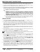
IMPORTANT SAFETY INSTRUCTIONS IMPORTANT SAFETY INSTRUCTIONS SAVE THESE INSTRUCTIONS! This manual contains important safety and operating instructions as prescribed by UL Standards for the Trace™ SW Series Inverter/Chargers for use in residential and commercial applications. This manual specifically covers products with the revision 4.01 software.
IMPORTANT SAFETY INSTRUCTIONS 3. Use of battery cable or custom attachment not recommended or sold by Xantrex Technology Inc. for the SW Series Inverter/Charger may result in a risk of fire, electric shock, or injury to persons. 4. Do not disassemble the inverter/charger. Take it to a qualified service center when service or repair is required. Incorrect re-assembly may result in a risk of electric shock or fire. 5.
IMPORTANT SAFETY INSTRUCTIONS 10. GROUNDING INSTRUCTIONS - This inverter/battery charger should be connected to a grounded, permanent wiring system. For most installations, the negative battery conductor should be bonded to the grounding system at one (and only one point) in the system. All installations should comply with national and local codes and ordinances. Refer to the SYSTEM GROUNDING section on page 26 for more information. PERSONAL PRECAUTIONS 1.
IMPORTANT SAFETY INSTRUCTIONS Page 4 2001 Xantrex Technology, Inc. 5916 - 195th Street N. E. Arlington, WA 98223 Telephone: 360/435-8826 Fax: 360/435-2229 www.traceengineering.com SW Series Inverter/Charger Part No. 2031-5 Rev.
INTRODUCTION INTRODUCTION Congratulations! You are the proud owner of the finest inverter on the market today - and one very complex piece of equipment. The Trace™ Sine wave (SW Series) Inverter/Charger has many features and capabilities previously either non-existent, or found only in separate products. With proper installation, the inverter will operate satisfactorily for many applications straight out of the box, using the factory default settings.
INTRODUCTION Page 6 2001 Xantrex Technology, Inc. 5916 - 195th Street N. E. Arlington, WA 98223 Telephone: 360/435-8826 Fax: 360/435-2229 www.traceengineering.com SW Series Inverter/Charger Part No. 2031-5 Rev.
UNIT IDENTIFICATION UNIT IDENTIFICATION This section describes the marking and location of the model and serial numbers for SW Series Inverter/Chargers. Use this section to determine the type and model of your inverter/charger. The unit identification label on the left side panel of the inverter/charger will show the serial number, model number, listings, ratings, and date of manufacture.
UNIT IDENTIFICATION Page 8 2001 Xantrex Technology, Inc. 5916 - 195th Street N. E. Arlington, WA 98223 Telephone: 360/435-8826 Fax: 360/435-2229 www.traceengineering.com SW Series Inverter/Charger Part No. 2031-5 Rev.
CONTROLS, INDICATORS AND COMPONENTS CONTROLS, INDICATORS AND COMPONENTS The SW Series Inverter/Chargers have an integral, full function Control Panel with LED status indicators. The following components are also included: inverter/charger circuit breaker; battery temperature sensor (BTS) port, remote port, and a stacking port.
CONTROLS, INDICATORS AND COMPONENTS CONTRAST CONTROL The CONTRAST adjustment enables you to adjust the contrast of the LCD display screen to accommodate changing lighting conditions. Less contrast is usually preferable in brighter lighting conditions. RESET TO FACTORY DEFAULTS BUTTON The RESET TO FACTORY DEFAULTS button returns all of the inverter settings (except for the TIME OF DAY settings) to the factory default values.
CONTROLS, INDICATORS AND COMPONENTS AC1 IN GOOD (Green) Indicates that AC power is present at the AC HOT IN 1 and NEUTRAL IN 1 input terminals. This input is intended for utility power. When an AC source is connected to the input terminals, it will start to blink slowly (once a second) to show the AC voltage has been detected. After the inverter has connected to the AC source, the LED will be solid. If the LED starts to blink during operation, utility power has been dropped.
CONTROLS, INDICATORS AND COMPONENTS AC SIDE Figure 4 shows the components located on the AC side of the inverter. The removable AC Access Panels cover and protect the Internal Components and Indicators, such as the AC Terminal Block, BTS Connection, LED status indicators (for the AC1 and Gen Control relays) and the Aux and Gen Control relay terminals. Refer to the INSTALLATION section beginning on page 15, for all wiring connections.
CONTROLS, INDICATORS AND COMPONENTS INTERNAL COMPONENTS AND INDICATORS Additional components and indicators are located behind three removable AC Access Panels located on the AC Side of the unit. They include the AC Terminal Block, BTS Connector, three LED indicators and the Aux and Gen Control Relay Connectors.
CONTROLS, INDICATORS AND COMPONENTS AC SAFETY GROUND The AC Safety Ground is used to connect the inverter chassis to the AC Grounding System. AUXILIARY AND GENERATOR CONTROL RELAY CONNECTORS Generator Control Relay Connectors Auxiliary Control Relay Connectors Figure 6, Auxiliary and Generator Control Relay Connectors DC SIDE Figure 5 shows the components located on the DC side of the inverter.
INSTALLATION INSTALLATION This section is very important, since it tells you how to properly install your SW Series Inverter/Charger. It becomes very frustrating when your inverter system does not perform properly, simply because care was not taken during installation. Please read this entire section carefully. You will save time and avoid common mistakes. This section also describes the requirements and recommendations for installing the SW Series Inverter/Charger. In the U.S.
INSTALLATION QUICK INSTALL This section provides installers, licensed electrical contractors, and knowledgeable laymen the essential steps to quickly install the Trace™ SW Series Inverter/Charger. If you haven’t had experience with the SW Series Inverter/Charger, you are urged to skip this section and read the entire INSTALLATION section before installing the inverter/charger. MOUNTING Mount the unit securely in a clean, dry, properly ventilated enclosure.
INSTALLATION COMPLETE INSTALL UNPACKING Before beginning, unpack the inverter/charger; record the serial number on the inside cover of this booklet and on the warranty card. Right now, please do the following: • Verify that you have everything listed on the Packaging Materials sheet. If any items are missing, please call Customer Service at (360) 435-8826. • Save your “proof-of-purchase”, You will need the “proof-ofpurchase” to obtain warranty service. • Keep the original carton and packing materials.
INSTALLATION Use 1/4" minimum diameter bolts for mounting. The mounting must be capable of supporting twice the weight of the inverter in order to comply with UL 1741. If this unit is used in a mobile application (i.e. RV, Boat) secure the inverter to a shelf or deck to prevent movement. Place flexible washers on the mounting screws or bolts between the shelf or deck and the inverter chassis to reduce vibration.
INSTALLATION Note: The three neutral terminals are common to each other and can be used in any combination or order. In a residential application, it is often easier to only connect one AC neutral wire to the inverter and make the other neutral connections at a central point such as in the AC load center, etc. In mobile installations, the AC system must have the neutral physically isolated from the ground throughout the load distribution powered by the inverter.
INSTALLATION AC INSTALLATION GUIDELINES The following steps are a basic guideline for installation and connection of the AC wiring into and out of the inverter. 1. Disconnect the inverter from the battery bank (if already connected), by either removing the DC side fuse, or opening the DC disconnect. Then remove the AC wiring compartment cover from the front of the inverter by removing the two screws on the cover. 2.
INSTALLATION 120 VAC GROUND FAULT INTERRUPT OUTLETS (GFI’S) Xantrex has tested the following 120 VAC GFI’s and found them to work satisfactorily with our inverters: LEVITON PASS & SEYMOR ACE Hardware 6599 1591 4A957 ACE 33238 WARNING LABEL A warning label is provided to inform all personnel that an inverter is installed in your electrical system. This label should be installed at the electrical panel that is being powered by the inverter.
INSTALLATION DC WIRING CAUTION: The inverter’s maximum peak current requirements are high. If battery cables are too small and/or connections are loose, efficiency and maximum output power are degraded. Small cables or loose connections may cause dangerous overheating and a fire. BATTERY CABLE SIZING The larger the battery cables the better. Undersized cables result in additional stress on the inverter, lower efficiency, reduced surge power and lower peak output voltage.
INSTALLATION DC DISCONNECT AND OVERCURRENT PROTECTION For safety and to comply with regulations, battery over-current protection is required. Fuses and disconnects must be sized to protect the wiring in the system. The fuse or disconnect is required to open before the wire reaches its maximum current carrying capability. For residential and commercial electrical systems, the National Electrical Code requires both overcurrent protection and a disconnect switch.
INSTALLATION BATTERY CABLE CONNECTIONS Cables must have crimped (or preferably, soldered and crimped) copper compression lugs unless aluminum mechanical lugs are used. Soldered connections alone are not acceptable. We suggest using high quality, UL-listed Xantrex battery cables. These cables are available in a specific assortment of sizes from 1-½ to 10 feet, and in 2/0 or 4/0 AWG. They are color-coded and have pressure-crimped, sealed-ring terminals. Contact your Xantrex dealer to order.
INSTALLATION CONTROL WIRING More advanced installations will require additional wiring to interface the inverter to other components of the system. Proper installation is important to ensure the reliability of the system. Although the circuits may carry little or even no actual power, the use of quality wire in conduit is recommended to provide good results.
INSTALLATION SYSTEM GROUNDING GROUNDING INSTRUCTIONS - This inverter/charger should be connected to a grounded, permanent wiring system. For most installations, the negative battery conductor should be bonded to the grounding system at one (and only one point) in the system. The subject is more easily discussed if it is divided into three separate subjects; Chassis Ground, Ground Rods and Bonding. The grounding requirements vary by country and application.
INSTALLATION In some countries, the neutral is not bonded to the grounding system. This means you may not know when a fault has occurred since the overcurrent device will not trip unless a “double” fault occurs. In some marine electrical codes, this type of system is used. NEUTRAL-TO-GROUND BOND SWITCHING (RV AND MARINE APPLICATIONS) As required by NEC code and UL specification 458, inverter/charger installations in the U.S. that are used in RV or Marine applications employ ground-to-neutral switching.
INSTALLATION NEUTRAL-TO-GROUND “BOND” is provided by an external AC source for the entire AC system INVERTER (AC Terminal Block) NEUTRAL-TO-GROUND SWITCHING RELAY (Provided in the AC installation): Connects the neutral from external AC source, and neutral of the AC panel loads together when AC is applied to the inverter input.
INSTALLATION GROUNDING VS. LIGHTNING This information is intended to provide basic grounding techniques that will help prevent inverter damage due to lightning. It is not intended to be a complete course on grounding or a guarantee against protection during a lightning strike situation. The NEC is the ultimate authority as to legitimate grounding techniques for your electrical system.
INSTALLATION Page 30 2001 Xantrex Technology, Inc. 5916 - 195th Street N. E. Arlington, WA 98223 Telephone: 360/435-8826 Fax: 360/435-2229 www.traceengineering.com SW Series Inverter/Charger Part No. 2031-5 Rev.
FUNCTIONAL TEST FUNCTIONAL TEST Once the AC and DC wiring have been installed and connected, take a moment to go back over all connections and make sure they are secure and have been installed properly. Ensure that there is no AC or DC power provided to the inverter/charger and that all AC loads are disconnected from the output of the inverter. The below steps will complete a functional test of the inverter. If any area fails, figure out why before proceeding.
FUNCTIONAL TEST Page 32 2001 Xantrex Technology, Inc. 5916 - 195th Street N. E. Arlington, WA 98223 Telephone: 360/435-8826 Fax: 360/435-2229 www.traceengineering.com SW Series Inverter/Charger Part No. 2031-5 Rev.
MENU SYSTEM MENU SYSTEM OVERVIEW The operation of the inverter is determined by the settings in the menu system. The menu system is divided into a USER MENU and a SETUP MENU. Each of the menu systems is divided into MENU HEADINGS and MENU ITEMS. The menu headings break the menu into groups of related menu items. At the Menu Item level a setting can be adjusted, a mode can be selected or information can be displayed.
MENU SYSTEM USER MENU MAP Menu Heading Menu Item Setpoint The values shown are the factory default values for Model SW2512. See the USER and SETUP menu item descriptions for default values for other models.
MENU SYSTEM SETUP MENU MAP The SETUP MENU provides all the controls and settings needed when installing or adjusting the system. To access the SETUP MENU, press both the red ON/OFF MENU and green GEN MENU buttons on the Control Panel at the same time. To exit the SETUP MENU, press the red ON/OFF MENU button or press the down MENU HEADING button until you reach the USER MENU (menu headings 1-8).
MENU SYSTEM USER MENU The USER MENU provides all the controls and settings needed on a daily basis. It allows you to turn on the inverter and generator, read the AC and DC meters, check on an error cause and even adjust the inverter’s time clock. MENU HEADINGS Inverter Mode 1 Generator Mode 2 Trace Engineering Allows control of the inverter and enables the search and charger only modes. Allows control of the generator, enables automatic operation or triggers an equalization charge cycle.
MENU SYSTEM INVERTER MODE (1) MENU HEADING Set Inverter OFF SRCH ON CHG Allows turning the inverter ON and OFF, enabling the SEARCH mode or selecting the charger only mode CHG. The inverter always starts in the OFF position when powered up. Pressing the red ON/OFF MENU button on the control panel can also access this display. Use the SET POINTS button to move the single space cursor under the desired selection or you can continue to push the red button to move the cursor to the right.
MENU SYSTEM • ON - Starts the generator that is controlled by the inverter. If this position is selected, it will manually turn on the generator that is connected to the GEN CONTROL relays. The OFF position must be selected to manually turn the generator off. • EQ - Triggers the battery charger to complete the equalization process. If an AC source is connected to the AC HOT IN 1 terminals, then the equalization process will begin.
MENU SYSTEM Load Start Amps Ready NO If YES is displayed, it indicates that the automatic control system has started or is about to start the generator because the AC load current has reached the LOAD START AMPS setting. The automatic start is delayed by the time period set by the LOAD START DELAY MIN setting in the GEN AUTO START SETUP (12). This allows checking why the generator was automatically started.
MENU SYSTEM METERS (4) MENU HEADING The current meters provided measure only the real, in phase component of the current. This is the portion of the power that actually uses power from the battery. This allows better estimation of the DC power drawn by the load or the battery charger. This may cause the reading to vary from other AC meters. NOTE: The meters do not display a (+) symbol for positive values. Inverter/charger Amps AC 00 All models Range: -64 to +64 Amps Reads AC amperage.
MENU SYSTEM Grid (AC1) volts AC 120 Standard models Range: 00 to 255 VAC Grid (AC1) volts AC 230 “E” models Range: 00 to 510 VAC Grid (AC1) volts AC 105 “J & K” models Range: 00 to 255 VAC Grid (AC1) volts 220 “W” models Range: 00 to 510 VAC Reads the RMS value of the AC voltage at the inverter’s AC HOT 1 input and NEUTRAL IN 1 terminals. This is usually the connection for the utility grid. Value will drift around before inverter has synchronized.
MENU SYSTEM High Battery voltage NO Battery voltage was above the HIGH BATTERY CUT OUT VDC setting. This can be caused by the solar array or other charging source not being regulated. Check the controller for proper operation. Some controllers have a “equalize” setting which over-rides the normal operation, allowing the battery voltage to be unregulated. Return the controller to the “normal” setting and check for proper operation.
MENU SYSTEM The ERROR LED can be used to indicate when the generator frequency is well adjusted. When the frequency is within ± 5% of the nominal value, the LED will be off. Once outside this window, the LED will be on. A frequency meter is also provided in the METERS (4) menu heading to allow a more precise adjustment of the generator. It is able to indicate the frequency of the generator only after the inverter has been able to synchronize to the generator.
MENU SYSTEM SETUP MENU The SETUP MENU provides all the controls and settings needed when installing or adjusting the system. To access the SETUP MENU, press both the red ON/OFF MENU and green GEN MENU buttons at the same time on the control panel of the inverter or remote control. To exit, simply go to one of the USER MENU headings numbers 1 through 8, or press the red ON/OFF MENU or green GEN MENU button once. MENU HEADINGS Inverter Setup 9 Use to program and adjust the operation of the inverter.
MENU SYSTEM INVERTER SETUP (9) MENU HEADING Set Grid Usage FLT SELL SLT LBX • FLT - Float will try to maintain the batteries at the float voltage level. This can be used when the source of power is a utility grid or a generator. When AC power is available, the inverter will complete a full three stage charge cycle and then hold the battery at the float level until the source of utility power is no longer available.
MENU SYSTEM Set Low Battery cut out VDC 11.0 Set Low Battery cut out VDC 22.0 Set Low Battery cut out VDC 44.0 12 VDC models Range: 08.0 to 16.0 24 VDC models Range: 16.0 to 32.0 48 VDC models Range: 32.0 to 64.0 This setting controls when the inverter turns off due to a low battery voltage condition. The inverter will turn off only after this level has been reached for the period of time set by the following item.
MENU SYSTEM BATTERY CHARGING (10) MENU HEADING Note: See the battery section of this manual for recommended setting for different battery types. Set Bulk volts DC 14.4 12 VDC models Range: 10.0 to 16.0 Set Bulk volts DC 28.8 24 VDC models Range: 20.0 to 32.0 Set Bulk volts DC 57.6 48 VDC models Range: 40.0 to 64.0 Sets the voltage level that will be maintained during the first and second stage of the charging process. This will be the maximum voltage at which the batteries will be charged.
MENU SYSTEM Set Max Charge amps AC 20 12 VDC models Range: 01 to 25 Set Max Charge amps AC 30 24 VDC & 48 VDC models Range: 01 to 35 Set Max Charge amps AC 15 “E & W” models Range: 01 to 18 Set Max Charge amps AC 35 “J & K” models Range: 02 to 40 Sets the maximum amount of AC input current that the battery charger will use to charge the battery. This can be used to limit the charger output as well.
MENU SYSTEM GEN AUTO START SETUP (12) MENU HEADING Set Load Start amps AC 33 All models Range: 00 to 63 Sets the AC load current that will initiate the automatic generator control system when the current remains above this setting continuously for the LOAD START DELAY MIN period. Set Load Start delay min 05.0 All models Range: 00.0 to 25.
MENU SYSTEM Set Exercise period days 30 All models Range: 00 to 255 Sets a maximum number of days allowed between operation of the generator. When an internal counter reaches the number of days set, the generator will be started at the END QUIET TIME menu item setting. The run time is fixed at 10 minutes. If the generator is manually or automatically operated for 5 minutes at any time during this period, then this counter will reset and the period will start again.
MENU SYSTEM Set Pre Crank seconds 10 All Models Range: 00 to 255 Sets the number of seconds the system delays closing of relay RY8 - the star signal relay - once relay RY7 is closed. See the AUTOMATIC GENERATOR CONTROL MODE for more information. This period may also be the amount of time that the glow plugs will be on if they are connected to the automatic control system.
MENU SYSTEM Set Relay 9 volts DC 14.5 12 VDC Models Range: 05.0 to 17.6 Set Relay 9 volts DC 29.0 24 VDC Models Range: 10.0 to 35.5 Set Relay 9 volts DC 58.0 48 VDC Models Range: 20.0 to 71.0 Sets the voltage trip point for the auxiliary relay number 9. This setting is compensated for the battery temperature when using the BTS. There is no intentional time delay on the reaction for this setting. This allows fast response to rapid voltage changes in the system. R9 Hysteresis volts DC 01.
MENU SYSTEM BULK CHARGE TRIGGER TIMER (15) MENU HEADING Set Start Bulk time 00:00 All Models Range: 00:00 to 23:50 Starts the bulk charge process at the time shown. Setting to 00:00 defeats this function. This setting should be enabled when using the SLT mode so that the batteries are charged once each day. With the GRID USAGE TIMER enabled, the START BULK TIME setting should be set near the beginning of the charging time window for best operation.
MENU SYSTEM BATTERY SELLING (17) MENU HEADING Note: See the battery section of this manual for recommended settings for different battery types. Set Battery Sell volts DC 13.4 Set Battery Sell volts DC 26.8 Set Battery Sell volts DC 53.6 12 VDC models Range: 5.0 to 16.0 24 VDC models Range: 10.0 to 32.0 48 VDC models Range: 20.0 to 64.0 Sets the level to which the batteries will be discharged when power is being sold from the batteries to the grid.
MENU SYSTEM In either mode, the SET START BULK TIME menu item setting under the BULK CHARGE TRIGGER TIMER (15) menu heading can be used to increase the battery charging regulation voltage to the BULK VOLTS DC setting. Note: By setting the beginning time equal to the ending time, the grid usage timer feature is defeated. INFORMATION DISPLAY The following information is displayed as additional Menu Items. After Start Charge time: SELL mode charges battery. FLT mode charges battery.
MENU SYSTEM Page 56 2001 Xantrex Technology, Inc. 5916 - 195th Street N. E. Arlington, WA 98223 Telephone: 360/435-8826 Fax: 360/435-2229 www.traceengineering.com SW Series Inverter/Charger Part No. 2031-5 Rev.
OPERATION OPERATION The SW Series Inverter/Charger can be configured as a simple stand-alone unit, working in conjunction with your generator to handle loads too large for the generator alone, allowing two-wire or three-wire generators to be turned on and off based on battery voltage or loads amp size, or functioning as a utility interactive inverter which will allow you to send excess power back to the utility grid.
OPERATION Figure 18, Trace™ SW Series Inverter Output Waveform The inverter is able to synchronize with other AC sources before connecting it to the AC load. The frequency of the AC source is tracked and the inverter constantly adjusts its frequency to maintain a lock. A normally open contactor is used to parallel the inverter’s output and the AC source. The inverter’s power topology is bi-directional.
OPERATION POWER VS. EFFICIENCY There are two primary losses that combine to create the efficiency curve of the SW Series inverter. The first is the energy that is required to operate the inverter at full output voltage while delivering no current. This is the no load or idle power. At low power levels, the idle power is the largest contributor to efficiency losses. At high power, the largest source of loss is a result of the resistance in the transformer and power transistors.
OPERATION INVERTER CAPACITY VS TEMPERATURE The current protection circuit in the SW Series Inverter/Charger is temperature compensated, therefore the maximum sized load that the inverter can run changes with temperature. As the temperature of the power devices (FET’s) increase, the allowable current is reduced. When the available current is reduced, the capacity of the inverter to run loads is reduced.
OPERATION OPERATING MODES The SW Series Inverter/Charger can be used in a wide variety and combination of operating modes: • Inverter Mode - DC to AC inverter with sine wave output, high starting surge, power saving search mode, low idle current, and very high efficiency DC to AC conversion. • Charger Mode - Low AC current distortion, three stage, temperature compensated, high amperage battery charger.
OPERATION INVERTER MODE BATTERY DC INVERTER AC AC LOADS IN BRIEF The inverter makes a stepped approximation to a sine wave. The number of steps typically varies from 34 to 52 per cycle. Lower battery voltage and/or higher output power level increases the number of steps. Higher battery voltage decreases the number of steps. Distortion varies from 3% to 5%.
OPERATION Example A: If the SEARCH WATTS is set at 32 and a 30-watt incandescent light is turned on, the inverter will detect the light. The initial load of the bulb is much greater than 32 watts when its filament is cold. When the light gets bright, the filament heats up and the light becomes a 30-watt load. Since this is below the setting of 32, the inverter will not detect it and the light will turn off. This can cause cycling of the inverter between on and off.
OPERATION CHARGER MODE AC SOURCE AC CHARGER BATTERY DC IN BRIEF When AC power is available, the inverter can operate as a very powerful battery charger with low current distortion. Power is drawn over the full AC cycle. This improves the performance with low AC input voltage or with small generators.
OPERATION BATTERY TEMPERATURE SENSOR (BTS) A plug-in external Battery Temperature Sensor (BTS), which is provided, automatically fine-tunes the charging process of the battery charger in relation to temperature. When the temperature sensor is installed, the charge voltage is adjusted either higher or lower than the BULK and FLOAT setpoints based on temperature. The BATTERY TEMP COMP VOLTS DC menu item under the METERS (4) menu heading shows this adjusted charge voltage.
OPERATION AC CURRENT LEVEL The maximum current draw into the AC HOT IN 1 terminal can be adjusted by the SET GRID (AC1) AMPS AC menu item. The maximum current draw into the AC HOT IN 2 terminal can be adjusted by the SET GEN (AC2) AMPS AC menu item. These adjustments are used to “back off” the battery charger’s AC current draw while other AC loads are being powered through the inverter. This prevents the overloading of the AC source and prevents nuisance tripping of the AC source circuit breakers.
OPERATION Once the battery voltage nears the BULK VOLTS DC setting, the voltage will be held at this level while the current into the battery tapers off. The time allowed for this tapering period is called the ABSORPTION TIME period. This setting is very important for systems which use generators since it determines how long a generator will run and when the generator shuts off. Using a generator to “trickle” charge a battery is not efficient and should be avoided.
OPERATION The battery manufacturer or supplier should be consulted before equalizing to provide the recommended process and settings. During the equalization process, check the temperature of each battery every hour by momentarily feeling the battery case. If the batteries are excessively warm (too hot to keep your hand on), terminate the charging immediately. Let the batteries cool before checking the need for further equalization charging.
OPERATION INVERTER/CHARGER MODE UTILITY GRID AC INVERTER/ CHARGER AC AC LOADS AC DC GENERATOR BATTERY IN BRIEF The SW Series Inverter/Charger is capable of automatically transferring AC loads from the inverter to a utility grid or generator. Once transferred, the inverter can recharge the battery. The inverter/charger can transfer upon the availability of AC power (FLT mode), either at a specific time each day (using the GRID USAGE TIMER (18) menu heading), or upon a low battery condition (LBX mode).
OPERATION While connected to the utility, the battery charger will be engaged. Some applications may want to allow the alternate power source (solar, wind or hydro) to recharge the battery instead of allowing the utility to provide the power. The only option is to program the SET MAX CHARGE AMPS AC menu item under the BATTERY CHARGING (10) menu heading to the minimum value, 1 amp AC, and set the BULK VOLTS and FLOAT VOLTS settings, also under the BATTERY CHARGING (10) menu heading, to a low value.
OPERATION GENERATOR SUPPORT MODE GENERATOR AC INVERTER/ CHARGER AC AC LOADS DC BATTERY IN BRIEF The factory default settings are intended to operate the inverter as an inverter/charger connected to a generator. When the generator is off, the inverter will power the AC loads from the battery. Once the generator is started, the AC loads will be transferred to the generator and the inverter will become a battery charger and store the unused power in the batteries for later use.
OPERATION GENERATOR SUPPORT/OVERLOAD PROTECTION This battery charger is quite powerful and, without limits, could overload a generator. When the generator is running, it has to power both the battery charger and any connected AC loads. If the AC load current, combined with the charge current, exceeds the SET GEN (AC2) AMPS AC setting, the charge rate will automatically be reduced to avoid overloading the generator or tripping its circuit breaker.
OPERATION AUTOMATIC GENERATOR CONTROL MODE GENERATOR AC CONTROL INVERTER/ CHARGER AC AC LOADS DC BATTERY IN BRIEF Automatic start/stop control of a back-up generator can be used with any of the other operating modes. If used with an application that includes utility power, the generator will be started only if the utility power is not available. It is not possible to use both generator and utility power at the same time.
OPERATION GEN CONTROL RELAYS CAUTION: All circuits connecting the auto generator control system MUST be protected with fuses rated at 5 amps or less. The warranty does not cover damage to these relays. Fuses should be located as close as possible to the point of connection to the larger conductors providing power from the battery.
OPERATION (3) Time (Exercise Period Days): The generator is automatically started at a pre-selected time whenever it exceeds a set number of days without running. Once the start command is initiated, the generator starts and runs for 15 minutes to ensure that it remains fully operational and that the generator’s starting battery is maintained at an optimal state of charge. To set generator start time, go to END QUIET TIME under the GENERATOR TIMER menu.
OPERATION GENERATOR AUTO START REQUIREMENTS AND TYPES In order for the generator to be automatically started, it must include electric start and an automatic choke. An automatic primer system may also be required on natural gas and propane powered generators. The generator should also include remote start ability with accessible remote start terminals or a connector.
OPERATION THREE-WIRE START GENERATORS Three-wire start generators do not include automatic engine cranking control system. Separate control of the starter motor requires additional interaction between the inverter’s auto-control system and the generator. This also adds complexity to the installation since more wires must be connected and more programming of the inverter is required. Troubleshooting can also be more difficult.
OPERATION Most diesel generators are controlled like the Onan type, except that they also require that glow plugs be operated before the generator start is attempted. The SW Series Inverter/Charger automatic generator control system can also provide glow plug control. The addition of an external relay may be required to operate the glow plugs due to the amperage required by the glow-plugs and to separate the stop signal circuit.
OPERATION GENERATOR STOP COOL DOWN PERIOD When the automatic generator stop system is used to stop the generator, the generator is disconnected from the inverter first by opening the AC relay inside the inverter. This allows a very clean transition from the generator to the inverter. The STOP signal is provided immediately if the generator is manually shut off from the Control Panel.
OPERATION EQUALIZATION CHARGING, AUTOMATIC GENERATOR CONTROL SYSTEM An automatic equalization charge process is available in the SW Series Inverter/Charger. To start the equalization process, select EQ from the SET GENERATOR menu item, accessible by pressing the green GEN MENU button on the Control Panel. During the next automatic generator run period, the inverter can be set to complete an equalization charge process. You must first select EQ from the SET GENERATOR menu item.
OPERATION UTILITY BACKUP MODE UTILITY GRID GENERATOR AC AC MAIN AC BREAKER PANEL INVERTER/ CHARGER AC AC ADDITIONAL AC BREAKER SUB-PANEL AC DC AC NON-CRITICAL AC LOADS BATTERY CRITICAL AC LOADS IN BRIEF SW Series Inverter/Chargers provide an excellent utility system backup under the majority of powering applications. Whenever a shorted grid condition affects voltage or frequency, the inverter disconnects itself from the grid and continues to support the AC load using battery power.
OPERATION UTILITY SUPPORT/OVERLOAD PROTECTION This battery charger is very powerful and without limits could draw more current than is available from the AC input source. When the utility grid is available, the grid has to power both the battery charger and any AC loads connected. If AC charge current combined with any AC load current exceeds the GRID (AC1) AMPS AC menu item setting, the charge rate will be automatically reduced to keep from tripping the utility grid breaker.
OPERATION UTILITY INTERACTIVE MODE UTILITY GRID kWh METER AC MAIN AC LOADS NOT PROVIDED WITH BACK-UP SOLAR ARRAY DC AC OUTDOOR AC DISCONNECT AC AC BACKED UP AC LOADS SUB-PANEL INVERTER/ CHARGER GROUND FAULT PROTECTION DC DC BATTERY DC OVERVOLTAGE PROTECTION IN BRIEF In this mode, SW Series Inverter/Chargers can be used to move power from the DC system into the AC utility grid. This is often called “selling” power since the utility pays for the power you produce.
OPERATION THEORY OF OPERATION When SELL mode is selected from the SET GRID USAGE menu item located under the INVERTER SETUP (9) menu heading in the SETUP MENU, the inverter will move any excess power not required to charge the batteries into the utility grid. In SELL mode, the inverter can be thought of as a battery charger that is able to operate in either direction - it can send excess power from the battery back into the utility grid instead of drawing power from the utility to charge the battery.
OPERATION SELLING POWER - FROM A DC CHARGING SOURCE The simplest and default operation of the SW Series Inverter/Charger in the SELL mode is to “sell” the excess power from the charging source to the utility when the batteries are full. In this mode, the battery voltage is held to the regulation level determined by the SET BATTERY SELL VOLTS DC setting.
OPERATION SELLING POWER - STORED IN THE BATTERIES Power stored in the batteries can also be sold into the utility grid. This can be used together with the solar array or alone without a solar array. The inverter can be programmed to sell the energy in the batteries at a specific time and then to recharge the batteries at another time. Both the discharge level and discharge rate can be adjusted to control the battery selling process.
OPERATION A system that includes 2400 watts of solar array is able to produce approximately 18 amps of AC power at 120 VAC. The output is most needed from 12:00 noon to 18:00 by the utility. If the GRID USAGE TIMER is set to a START CHARGE TIME of 18:00 and a END CHARGE TIME of 12:00 noon, the inverter will sell the battery from 12:00 noon to 18:00.
OPERATION UTILITY INTERACTIVE OPERATION WITH UTILITY BACKUP The SW Series Inverter/Charger is capable of operating both as a utility interactive and a stand-alone inverter. This allows the system to normally sell the excess power to the utility and, once an outage has occurred, provide power to the AC loads from the battery. The loads that will be provided with utility backup during outages must be isolated from the non-utility backed-up loads.
OPERATION OVERVOLTAGE PROTECTION FOR THE BATTERY IN SELL MODE Normally, the inverter will regulate the charging process of the battery by selling excess power into the utility grid. The battery will receive a three-stage charge routine as previously described. If the utility grid is not available (due to an outage or tripped AC input circuit breaker, etc.
OPERATION ENERGY MANAGEMENT MODE UTILITY GRID AC INVERTER/ CHARGER AC AC LOADS DC BATTERY IN BRIEF The purpose of this mode is to manage how utility power is used. One method is to charge the batteries at a favorable time and then use the power later. This is often desirable when time of day metering is available. A solar array is not required, but can be used to reduce the discharging of the battery.
OPERATION The system should be designed so that the battery is able to operate the loads for the entire peak rate period without reaching the low battery transfer voltage. This may require that heavy loads be operated only during the non-peak rate period. This mode may be advantageous when the utility offers time-of-day metering that allows you to buy power at a variable rate during different time periods. For example, the rate may be only $0.04 per kilowatt-hour from midnight to 6 AM, but $0.
OPERATION PEAK LOAD SHAVING MODE UTILITY GRID AC INVERTER/ CHARGER AC AC LOADS DC BATTERY IN BRIEF The inverter can also be used to limit the maximum draw the AC loads place on the utility grid. Many utilities impose a surcharge on their customers based on the peak load used by a facility. The SW Series Inverter/Charger can be configured to provide all of the power above a specified level, eliminating the surcharges.
OPERATION LOW BATTERY TRANSFER (LBX) MODE UTILITY GRID kWH METER AC LOADS SUB-PANEL SOLAR ARRAY AC DC AC AC LOADS MAIN PANEL AC INVERTER CHARGER GROUND FAULT PROTECTION DC DC BATTERY DC OVERVOLTAGE PROTECTION Low Battery Transfer mode is an alternative way of operating “off the grid” using the utility for backup power instead of a generator. The system essentially operates as a stand-alone power system, independent of the utility grid.
OPERATION Once the system has transferred back to the battery, the battery voltage will continue to increase if the power from the alternative source exceeds the loads. This can result in the battery voltage reaching the HIGH BATTERY CUT OUT VDC setting unless a charge control device limits the battery voltage. Note that the LOW BATTERY CUT IN VDC setting must be set below the external charge controllers regulation setting or the system would never transfer back to the battery.
OPERATION USING MULTIPLE INVERTERS Multiple SW Series Inverter/Chargers can be used in the same system. There are some limitations to the design of the system for successful and reliable operation. For North American applications, the inverters can be used in a “series” configuration to operate 240 VAC loads and to connect to 120/240 VAC power systems. Series stacking of “E” versions (230 VAC / 50 Hz) would result in 230/460 VAC power.
OPERATION 240 VAC/60 HZ ONLY ELECTRICAL SYSTEMS Two 120 VAC / 60 HZ inverters “series” stacked can be used to provide 240 VAC. This provides both 120 and 240 VAC since a center “neutral” is provided between the two inverters. If a 240 VAC only AC source is connected to the AC input terminals of the inverter without this center neutral, unacceptable operation will result.
OPERATION BATTERY CHARGING WITH MULTIPLE INVERTERS The inverters can operate in parallel as battery chargers from the same AC source connected to the same battery. The AC input terminals and DC terminals would all be in parallel. The inverters will synchronize individually to the AC source and then connect. When multiple inverters are connected to the same battery and operated as in battery charger mode, the settings of the inverters are best set to the same settings.
OPERATION Page 98 2001 Xantrex Technology, Inc. 5916 - 195th Street N. E. Arlington, WA 98223 Telephone: 360/435-8826 Fax: 360/435-2229 www.traceengineering.com SW Series Inverter/Charger Part No. 2031-5 Rev.
TECHNICAL INFORMATION TECHNICAL INFORMATION BATTERY TYPE This section of the manual is included to help you better understand the factors involved with battery charging, care, and maintenance, by discussing the physical make-up and characteristics of chemical storage batteries. This is not intended to be an exhaustive discussion of battery types, but simply a guideline. The manufacturer of each specific battery is the best authority as to its use and care.
TECHNICAL INFORMATION Type 8D batteries are available with either cranking or deep cycle construction. The deep cycle versions are 12-volt batteries rated at 200 amp hours or so. Since they are most commonly used to start truck engines, you should make sure you purchase the deep cycle version. SEALED LEAD ACID BATTERIES CAUTION: if using gelled batteries, the battery charger must be set to the appropriate settings or battery damage will occur.
TECHNICAL INFORMATION BATTERY SIZING Batteries are the inverter’s fuel tank. The larger the batteries, the longer the inverter can operate before recharging is necessary. An undersized battery bank results in reduced battery life and disappointing system performance. Batteries should not be discharged more than 50% of their capacity on a regular basis. Under extreme conditions (such as a severe storm or a long utility outage), cycling to a discharge level of 80% is acceptable.
TECHNICAL INFORMATION BATTERY BANK SIZING EXAMPLE Complete the steps that follow to calculate your inverter’s battery bank capacity. No two installations will require exactly the same battery bank capacity. The following example provides a guide for determining your needs. Read through the example and then complete the worksheet on the following page. STEP 1-4: Determine your Average Daily Watt-Hours Needed.
TECHNICAL INFORMATION WORKSHEET Complete the steps that follow to calculate your inverter’s battery bank capacity. STEP 1-4: Determine your Average Daily Watt Hours Needed. AC APPLIANCE STEP 1 STEP 2 STEP 3 STEP 4 APPLIANCE RUNNING WATTS (X) HOURS USED EACH DAY (X) DAYS USED EACH WEEK (÷ 7 = ) AVERAGE DAILY WATT HOURS NEEDED STEP 1: Determine what appliances the inverter will power and enter the Appliance Running Wattage of each appliance.
TECHNICAL INFORMATION BATTERY CARE AND MAINTENANCE If you have read the battery charger mode section of this manual, you already have a good idea of the stages of battery charging that combine to promote fast charging and ensure long battery life. Basically, there are five charger-related considerations to properly care for your batteries. • Charge Rate - The maximum safe charge rate is related to the size and type of your batteries.
TECHNICAL INFORMATION MONTHLY MAINTENANCE At the minimum, check the level of the electrolyte in each battery cell once a month. It should be above the top of the plates but not completely full. Most batteries have a plastic cup that the electrolyte should just touch when full. Don’t overfill the batteries or the electrolyte will spill out of the batteries when they are being charged.
TECHNICAL INFORMATION BATTERY INSTALLATION CAUTION: Batteries can produce extremely high currents if they are short-circuited. Be very careful when working around them. Read the important safety instructions at the start of this manual and the battery supplier’s precautions before installing the inverter and batteries. LOCATION Batteries should be located in an accessible location with nothing restricting the access to the battery caps and terminals on the tops.
TECHNICAL INFORMATION BATTERY HOOK-UP CONFIGURATIONS Battery banks of substantial size are generally created by connecting several smaller batteries together. There are three ways to do this. Batteries can be connected in series, to increase voltage; in parallel to increase amp-hour capacity; or in series – parallel, to achieve the required voltage and capacity. The cables which connect the individual batteries together to make a larger battery “bank” should be connected together will heavy cables.
TECHNICAL INFORMATION PARALLEL CONNECTION Batteries are connected in parallel when all the positive terminals of a group of batteries are connected and then, separately, all the negative terminals are connected. In a parallel configuration, the battery bank have the same voltage as a single battery, but an amp/hour rating equal to the sum of the individual batteries. This is usually only done with 12-volt battery-inverter systems.
TECHNICAL INFORMATION 6V 6V 6V 6V 6V 6V 6V 6V 6V 6V 6V 6V FUSED DISCONNECT FUSED DISCONNECT 12V INVERTER (Total Battery Capacity = 200 Amp Hours) 6V 24V INVERTER (Total Battery Capacity = 200 Amp Hours) 6V 6V 6V FUSED DISCONNECT 6V 6V 6V 6V 6V 6V 6V 6V 6V 6V 6V 48V INVERTER (Total Battery Capacity = 200 Amp Hours) Each individual 6-volt battery capacity = 100 amp hours NOTE: If “cross-tying” is not required, the “dash” (- - -) connections are not needed.
TECHNICAL INFORMATION BATTERY CABLE INDUCTANCE When current passes through a conductor a magnetic field is set up around the conductor. As this magnetic field builds, it induces voltage in any conductor that is close by, and it induces a voltage in the original conductor. The voltage induced into the original conductor is called self-inductance, and tends to oppose the current that produced it. The magnitude of the self-induced voltage is proportional to the size of the loop formed by a wire.
TECHNICAL INFORMATION APPLICATIONS RESISTIVE LOADS These are the loads that the inverter finds the simplest and most efficient to drive. Voltage and current are in phase, or, in this case, in step with one another. Resistive loads usually generate heat in order to accomplish their tasks. Toasters, coffee pots and incandescent lights are typical resistive loads. Larger resistive loads--such as electric stoves and water heaters--are usually impractical to run off an inverter.
TECHNICAL INFORMATION Page 1 TROUBLESHOOTING GUIDE INVERTER - If ERROR LED comes on, see ERROR CAUSES section PROBLEM Unit will not come on (no LED’s are on) and the Control Panel Display is blank or off Unit comes on, but goes off quickly (several attempts made) INDICATION SOLUTION DC voltage on the inverter’s DC terminals is incorrect.
TECHNICAL INFORMATION TROUBLESHOOTING GUIDE Page 2 BATTERY CHARGER - If ERROR LED comes on, see ERROR CAUSES section. PROBLEM AC IN GOOD LED is flashing, but will not start charging (allow 40 seconds to synchronize) INDICATION SOLUTION AC frequency at the AC input terminal is out-of- tolerance (too high or low) or AC voltage outside ‘Upper/Lower VAC limit’ settings If AC source is a generator, adjust AC voltage or frequency accordingly.
TECHNICAL INFORMATION TROUBLESHOOTING GUIDE Page 3 ERROR CAUSES - ERROR LED is On or Flashing (look under the ERROR CAUSES display) INDICATION SOLUTION OVER CURRENT Excessive load on the AC output Disconnect all wires on the AC input and output. TRANSFORMER OVERTEMP or HEATSINK OVERTEMP Charging: AC input voltage may be too high, check for high input ac voltage Unit is warm/hot to the touch Let inverter cool down and try restarting.
TECHNICAL INFORMATION INVERTER/CHARGER TERMINOLOGY The following is a glossary of terms with which you may not be familiar while reading this manual. They appear in the description of inverter and battery charger operation. Absorption Stage - In this second stage of three-stage charging, the batteries are held at a constant voltage (the bulk voltage setting) and the battery is charged to its maximum capacity. AC - Alternating Current. Electrical current that varies with time.
TECHNICAL INFORMATION Load(s) - Any electrical item which draws power. (i.e., lights, radio, washer/dryer, refrigerator, etc.) Locked Rotor Amps - The current drawn by an electric motor with the shaft or rotor stopped and locked in position. This can be used to determine if an inverter has enough surge current to start a motor. If the inverter is capable of producing more amperage than the locked rotor amps rating of a motor, it will most likely start the motor easily.
TECHNICAL INFORMATION Stacking: Series - Two inverters operating together to produce twice the power and voltage of a single inverter. Required when operating 240 VAC loads and separate 120 VAC loads from either inverter. Parallel - Two inverters operating together to provide twice the continuous and surge capacity on a single output circuit. Required when a single load is too large for one inverter. The units must be stackable, and an interface cable must be utilized.
TECHNICAL INFORMATION SPECIFICATIONS AND FEATURES (60 Hz Models) Note: All specifications are subject to change without notice.
TECHNICAL INFORMATION SPECIFICATIONS AND FEATURES (50 Hz Models) Note: All specifications are subject to change without notice.
TECHNICAL INFORMATION DIMENSIONS Figure 37, SW Series Dimensions: With AC Access Covers – Showing Knockout Sizes Page 120 2001 Xantrex Technology, Inc. 5916 - 195th Street N. E. Arlington, WA 98223 Telephone: 360/435-8826 Fax: 360/435-2229 www.traceengineering.com SW Series Inverter/Charger Part No. 2031-5 Rev.
TECHNICAL INFORMATION INSTALLATION DIAGRAMS The following diagrams and information is provided to assist you or your system installer with the design and installation of the Trace™ SW Series Inverter/Charger. Due to the variety of applications, models available, and differences in local and national electrical codes, these diagrams and information should be used as general guidelines only. You must consider your application and local and national electrical codes when designing and installing your system.
TECHNICAL INFORMATION Figure 39, Installation Diagram, 240 VAC, 3 Wire, Grid Connected, Generator Backup Page 122 2001 Xantrex Technology, Inc. 5916 - 195th Street N. E. Arlington, WA 98223 Telephone: 360/435-8826 Fax: 360/435-2229 www.traceengineering.com SW Series Inverter/Charger Part No. 2031-5 Rev.
TECHNICAL INFORMATION USER SETTINGS WORKSHEETS Your SW Series Inverter/Charger may have USER and/or SETUP operating settings that are different or are changed from the standard factory settings. The USER DEFAULT settings are the same for all models. The SETUP DEFAULT settings are dependent on the specific model of the SW Series Inverter/Charger. Worksheets are provided for domestic (US) models.
TECHNICAL INFORMATION SETUP MENU – 12 VDC (120 VAC/60HZ) MODELS To access the SETUP MENU, press the RED and GREEN buttons on your CONTROL PANEL (or SWRC) at the same time. To exit the Setup Menu, press the ON/OFF MENU button or use the down MENU HEADING button until you reach the USER MENU (menu headings 1 – 8). MENU HEADING Inverter Setup MENU ITEM SELECTION RANGE 9 Set Grid Usage FLT SELL SLT LBX FLT 0.80 – 25.5 11.
TECHNICAL INFORMATION SETUP MENU – 24 VDC (120 VAC/60HZ) MODELS To access the SETUP MENU, press the RED and GREEN buttons on your CONTROL PANEL (or SWRC) at the same time. To exit the Setup Menu, press the ON/OFF MENU button or use the down MENU HEADING button until you reach the USER MENU (menu headings 1 – 8). MENU HEADING Inverter Setup MENU ITEM SELECTION RANGE 9 Set Grid Usage FLT SELL SLT LBX FLT 16.0 – 35.5 22.
TECHNICAL INFORMATION SETUP MENU – 48 VDC (120 VAC/60HZ) MODELS To access the SETUP MENU, press the RED and GREEN buttons on your CONTROL PANEL (or SWRC) at the same time. To exit the Setup Menu, press the ON/OFF MENU button or use the down MENU HEADING button until you reach the USER MENU (menu headings 1 – 8). MENU HEADING Inverter Setup MENU ITEM SELECTION RANGE 9 Set Grid Usage FLT SELL SLT LBX FLT 32.0 – 70.0 44.
TECHNICAL INFORMATION 2001 Xantrex Technology, Inc. 5916 - 195th Street N. E. Arlington, WA 98223 Telephone: 360/435-8826 Fax: 360/435-2229 www.traceengineering.com SW Series Inverter/Charger Part No. 2031-5 Rev.
APPENDIX APPENDIX OPTIONS Options available for the SW Series Inverter/Charger include a choice of remote controls, and a battery temperature control. SWRC The optional SWRC Remote Control (SWRC or SWRC/50FT) has the ability to communicate with and adjust settings in the SW Series Inverter/Charger. It is operational whenever DC power is applied to the inverter DC input terminals.
APPENDIX OTHER PRODUCTS Contact your Xantrex dealer for details of any of the products below. C40 MULTI-FUNCTION CONTROLLER The C40 Multi-Function Controller may be used as a PV (solar) charge controller, DC load controller, or DC diversion regulator. The unit works with 12, 24, or 48 volts systems and is rated at 40 amps continuous capacity.
APPENDIX REFERENCE TABLES AND GRAPHS Table 9, Power Consumption Of Common Appliances TIME IN MINUTES APPLIANCE WATTS 5 15 30 60 120 240 Single PL Light 10 .1 .3 .7 1.3 2.7 5.3 B & W TV 50 .
APPENDIX SIZE DIAMETE R SIZE DIAMETE R 14 12 .073 .072 2/0 .420 3/0 .475 10 .115 8 .146 4/0 .530 6 .184 4 .235 250 MCM .580 3 .281 300 MCM .635 2 .295 350 MCM .690 1 .335 400 MCM .730 1/0 .380 500 MCM .820 Note: Sizes shown are for the conductor – do not include any insulation when determining your wire size. Figure 40, AWG Wire Size Table 11, Minimum Recommended Battery Cable Size vs.
APPENDIX Table 13, Recommended Minimum AC Wire Sizes (75° C) • INVERTER MODEL FULL PASS-THRU CAPABILITY FUSE/BREAKER REQUIRED CABLE SIZE REQUIRED IN CONDUIT CABLE SIZE REQUIRED IN “FREE AIR”* 105-120 VAC UNITS 60 amps 60 amps # 6 AWG (THHN) # 8 AWG (THHN) 220-240 VAC UNITS 30 amps 30 amps # 10 AWG (THHN) # 10 AWG (THHN) The term "free air" is defined by the NEC as cabling that is not enclosed in conduit or a raceway.
APPENDIX Storage Checklist If the SW Series Inverter/Charger is used in a vehicular application such as a motor coach, truck, or boat, certain steps must be taken prior to seasonal storage. These steps are especially important for maintaining batteries as well as ensuring the automatic generator function, if installed, is disabled. Preparation for Storage Interior Storage • Check that all batteries are fully charged.
APPENDIX Page 134 2001 Xantrex Technology, Inc. 5916 - 195th Street N. E. Arlington, WA 98223 Telephone: 360/435-8826 Fax: 360/435-2229 www.traceengineering.com SW Series Inverter/Charger Part No. 2031-5 Rev.
WARRANTY/REPAIR INFORMATION WARRANTY/REPAIR INFORMATION LIMITED WARRANTY Xantrex Technology Inc. warrants its power products against defects in materials and workmanship for a period of two (2) years from the date of purchase and extends this warranty to all purchasers or owners of the product during the warranty period. This warranty is void under the following circumstances: (1) improper and/or unauthorized repair not provided by Xantrex Technology Inc.
WARRANTY/REPAIR INFORMATION WARRANTY OR REPAIR SERVICE REQUIRED If your product needs repair at the factory, it must be shipped fully insured in the original packaging or equivalent (shipping damage is not covered under warranty and will likely delay the repair and return of your unit). The shipper will not accept any damage claims – even if insured - on products damaged through improper packaging (i.e., peanuts, soft foam, undersized boxes, etc.). If possible, avoid sending products through the mail.
INDEX INDEX Absorption Time ..............................................................100 AC Inputs, Menu (11) ........................................................48 AC Pass Through Ability....................................................18 AC Safety Ground .............................................................14 AC Side .............................................................................12 AC Source Wired To Output, Menu ( 5).............................42 AC Terminal Block......
INDEX RESET TO FACTORY DEFAULTS Button ................... 10 Control Wiring ................................................................... 25 Aux Relay Wiring........................................................... 25 Fusing ............................................................... 25, 74, 89 Gen Control Relays ....................................................... 25 Remote Control Wiring.................................................. 25 Input Amps AC, Menu ( 4) ........................
INDEX Cool Down Period....................................................75, 79 Equalization Charging...................... 38, 47, 68, 79, 80, 97 Exercise Period .............................................................50 Frequency ...............................................................38, 42 Gen Control Wiring ........................................................25 Maximum Run Time ......................................................50 Spin Up ............................................
INDEX Menu ( 1) Inverter Mode .................................................... 37 Menu ( 2) Generator Mode ................................................ 37 Menu ( 3) Trace Engineering............................................. 39 Menu ( 4) Meters............................................................... 40 Menu ( 5) Error Causes..................................................... 41 Menu ( 6) Time of Day ...................................................... 43 Menu ( 7) Generator Timer......
INDEX Set Generator, Menu ( 2)...................................................37 Set Grid (AC1) Amps AC, Menu (11).................................48 Set Grid Usage, Menu ( 9).................................................45 Set High Battery Cut Out VDC, Menu ( 9)..........................46 Set Input Lower Limit VAC..................................... 71, 72, 73 Set Input Lower Limit VAC, Menu (11)...............................48 Set Input Upper Limit VAC ..........................................
INDEX User Settings .............................................................. 123 Setup Menu – 12 VDC ............................................ 124 Setup Menu – 24 VDC ............................................ 125 Setup Menu – 48 VDC ............................................ 126 User Menu .............................................................. 123 Page 142 2001 Xantrex Technology, Inc. 5916 - 195th Street N. E. Arlington, WA 98223 Telephone: 360/435-8826 Fax: 360/435-2229 www.
5916 - 195th Street N.E., Arlington, WA 98223 Phone: (360) 435-8826 visit our website at: www.traceengineering.