
- Xantrex International User's Manual Inverter/Charger PROsine 2.0


Configuration
4–18 445-0089-01-01
View Last 10 Panel
Faults
The display panel records the last ten faults that have occurred in the display
panel. You can view these for diagnostic and troubleshooting purposes. See
“Display Panel Faults” on page 6–9.
AC Bad Cause If the input AC is not acceptable according to the configuration values you set,
this screen indicates why: causes included low frequency, low voltage, etc. For a
complete list of causes, see “AC Bad Causes” on page 6–3.
View Software
Vers io ns
This information can help Xantrex Customer Service Representatives
troubleshoot problems you might have with the PROsine.
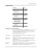
p LVP Software Revision
p HVP Software Revision
p Display Software Revision
p Display EEPROM Revision
View System
Temperatures
These readings show temperatures in the PROsine and the display panel.
PROsine HVDC This shows the voltage on the internal DC bus of the PROsine, when it’s operating
in Invert mode, Bypass, or Charge mode. This parameter will show 0V when the
unit is faulty or off mode. This can be helpful when troubleshooting with Xantrex
technical support.
Next Steps
At this point, you have configured the PROsine and display panel, and you are
now ready test and use the unit.
Go to “Part 1: System Startup Check” on page 5–2.