PS2.5 PS3.0 Installation and Operation Guide Xantrex ProsineTM 2.5 and 3.
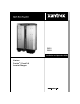
Prosine TM PS2.5 Inverter/Charger PS3.
About Xantrex Xantrex Technology Inc. is a world-leading supplier of advanced power electronics and controls with products from 50 watt mobile units to one MW utility-scale systems for wind, solar, batteries, fuel cells, microturbines, and backup power applications in both grid-connected and standalone systems. Xantrex products include inverters, battery chargers, programmable power supplies, and variable speed drives that convert, supply, control, clean, and distribute electrical power.
IMPORTANT SAFETY INSTRUCTIONS This manual contains important safety and operating instructions as prescribed by UL and CSA specifications for inverter/chargers. This manual covers PS 2.5 and PS 3.0, 12- and 24-volt model inverter/chargers. General Safety Precautions 1. READ AND SAVE THESE INSTRUCTIONS. They contain important safety and operating information for the Prosine inverter/charger. 2.
12. WARNING—RISK OF EXPLOSIVE GASES a) WORKING IN THE VICINITY OF A LEAD-ACID BATTERY IS DANGEROUS. BATTERIES GENERATE EXPLOSIVE GASES DURING NORMAL BATTERY OPERATION. BEFORE INSTALLING OR USING YOUR INVERTER/CHARGER, READ THIS MANUAL AND FOLLOW THE INSTRUCTIONS EXACTLY. b) This equipment contains components which tend to produce arcs or sparks. To prevent fire or explosion do not install in compartments containing batteries or flammable materials or in locations which require ignition protected equipment.
Important Safety Instructions FCC INFORMATION TO THE USER NOTE: This equipment has been tested and found to comply with the limits for a Class A digital device, pursuant to Part 15 of the FCC Rules. These limits are designed to provide reasonable protection against harmful interference when the equipment is operated in a commercial environment.
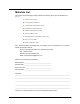
Materials List Your Prosine Inverter/Charger package includes the following items. (See the illustration on page vi.) 1. Prosine inverter/charger 2. Control panel with fasteners 3. Control panel communications cable 4. Red & black DC terminal covers 5. Installation and Operation Guide 6. Quick Installation Guide 7. Mounting brackets with fasteners (PS3.0 only). 8. Drip cover/vent shield 9.
Materials List System / Installation Information Before you call Customer Service, please record the following information about your system. It will help our staff to give you better service. ❐ Serial Number (This is on the side of the Prosine). ❐ Type of installation (e.g., RV, Boat, Home). ❐ Date of installation. ❐ Battery bank size. ❐ Battery type (e.g., flooded, sealed gel cell, AGM. ❐ AC service setting. ❐ AC wiring size and length. ❐ DC wiring size and length.
Figure 1. Inverter/Charger Components vi Prosine 2.5/3.
Warranty Warranty What does this warranty cover? This Limited Warranty is provided by Xantrex Technology, Inc. ("Xantrex") and covers defects in workmanship and materials in your Xantrex Prosine 2.5/3.0 Inverter/ Charger. This warranty lasts for a Warranty Period of 24 months from the date of purchase at point of sale to you, the original end user customer. This Limited Warranty is transferable to subsequent owners but only for the unexpired portion of the Warranty Period.
Disclaimer a) the product if it has been misused, neglected, improperly installed, physically damaged or altered, either internally or externally, or damaged from improper use or use in an unsuitable environment; b) the product if it has been subjected to fire, water, generalized corrosion, biological infestations, or input voltage that creates operating conditions beyond the maximum or minimum limits listed in the Xantrex product specifications including high input voltage from generators and lightning st
Warranty Warning: Limitations On Use Please refer to your product user manual for limitations on uses of the product. Specifically, please note that the Xantrex Prosine 2.5/3.0 Inverter/Charger is not intended for use in connection with life support systems and Xantrex makes no warranty or representation in connection with any use of the product for such purposes. Please note that the Xantrex Prosine 2.5/3.
Return Procedure x Prosine 2.5/3.
Contents Important Safety Instructions. . . . . . . . . . . . . . . . . . . . . . . . . . . . . . . . . . . . . . . . . . .i Materials List . . . . . . . . . . . . . . . . . . . . . . . . . . . . . . . . . . . . . . . . . . . . . . . . . . . . . .iv Warranty. . . . . . . . . . . . . . . . . . . . . . . . . . . . . . . . . . . . . . . . . . . . . . . . . . . . . . . . . vii Disclaimer. . . . . . . . . . . . . . . . . . . . . . . . . . . . . . . . . . . . . . . . . . . . . . . . . . . . . . . viii Product . .
Contents System Information Menu. . . . . . . . . . . . . . . . . . . . . . . . . . . . . . . . . . . . . . 18 Version Information Menu. . . . . . . . . . . . . . . . . . . . . . . . . . . . . . . . . . . . . . 19 Faults Display & Reset Button . . . . . . . . . . . . . . . . . . . . . . . . . . . . . . . . . . . . . . . 20 Inverter Status Indicators and On/Off Button . . . . . . . . . . . . . . . . . . . . . . . . . . . . 20 Power Indicator . . . . . . . . . . . . . . . . . . . . . . . . . . . . . . . . .
Contents Mounting to the Negative Battery Terminal . . . . . . . . . . . . . . . . . . . . . . . . 50 Mounting to the Side of the Battery Case . . . . . . . . . . . . . . . . . . . . . . . . . . 51 Typical System Diagrams . . . . . . . . . . . . . . . . . . . . . . . . . . . . . . . . . . . . . . . . . . . 52 Residential Backup System . . . . . . . . . . . . . . . . . . . . . . . . . . . . . . . . . . . . 52 Recreational Vehicle System . . . . . . . . . . . . . . . . . . . . . . . . . . . . . . . . . . .
Contents Equipment. . . . . . . . . . . . . . . . . . . . . . . . . . . . . . . . . . . . . . . . . . . . . . . . . . 74 Supplies . . . . . . . . . . . . . . . . . . . . . . . . . . . . . . . . . . . . . . . . . . . . . . . . . . . 74 Procedure . . . . . . . . . . . . . . . . . . . . . . . . . . . . . . . . . . . . . . . . . . . . . . . . . . 74 Cables. . . . . . . . . . . . . . . . . . . . . . . . . . . . . . . . . . . . . . . . . . . . . . . . . . . . . 75 Cabling & Hook-up Configurations . . . . . . . .
Section 1: Features Congratulations on your purchase of the Prosine inverter/charger. The Prosine inverter/charger uses advanced high-frequency switching technology in the power conversion process. The circuits are similar to those used in power supplies for computers and other modern electronic equipment.
Inverter Features Battery Temperature Shut Down When using the battery-temperature sensor, the charger will shut down if it detects excessively high or low battery temperatures. If battery temperature exceeds 50°C (122°F), or falls below -15°C (5°F), the charger will shut down. Adjustable Maximum AC Input Current This feature protects against nuisance tripping of AC circuit breakers on the utility or generator AC supply.
Section 1: Features Over-Current Protection When the AC loads connected to the Prosine inverter/charger exceed 50 amps, the inverter will instantaneously reduce the output voltage until the loads on the inverter are reduced. If the overload continues, the inverter will shut down. The unit will automatically restart after a calculated recovery time. High-Temperature Shut Down When the inverter detects a high-temperature condition internally, the inverter will shut down.
Inverter Features 4 Prosine 2.5/3.
Section 2: Controls and Indicators Prosine 2.5 inverter/chargers feature DC input and output connectors, an AC terminal block, a DIP switch panel for custom configuration, three accessory jacks, an LED control panel for the PS2.5 and an ACS panel for PS3.0, an LCD control panel, a cover for the AC connector block. The LCD control panel is optional on the PS2.5 and standard on the PS3.0. DC terminal covers come standard with both units.
AC Bypass Selector optimize the charging profile. The remote output jacks enable you to remotely mount the standard and/or the ACS control panels, described later in this section of this manual. AC Bypass Selector The small slide switch located between the Batt Temp jack and the Remote Output jacks is the AC Bypass selector switch. The default position of this switch is On. In the On position, the inverter/ charger operates as programmed.
Section 2: Controls and Indicators Standard LED Control Panel The Prosine inverter/charger is supplied with a control panel that can be mounted into an instrument panel, bulkhead or wall. The standard control panel is used to report information about Prosine operating parameters and the external AC and DC power sources connected to it.
Standard LED Control Panel Battery Status Indicator The Battery Status LED Display includes two vertical series of LEDs that indicate the battery voltage and current. A conversion table enables you to estimate the AC output from the inverter by the DC current. Battery Voltage Indicator This indicator reports the battery voltage at the input terminals of the Prosine inverter/charger. At low currents, the indicator is very accurate.
Section 2: Controls and Indicators Fault LED This LED flashes on-and-off during an error condition from which the unit will automatically recover and restart when the condition is remedied. The FAULT LED will be lighted steadily when any error occurs from which the inverter/charger cannot automatically recover. It is usually necessary to disconnect the AC or DC supply to recover from this type of error. An error condition is accompanied by an audible alarm if the alarm is enabled.
Standard LED Control Panel Power Indicator A green LED labeled UTILITY/SHOREPOWER (INCOMING) lights whenever AC power is supplied to the AC INPUT connectors on the inverter/charger. Throughout this manual, the term “shorepower” refers to the presence of AC power at the AC INPUT connectors, regardless of the source of the power: from the utility grid (power company), a generator, or any other source.
Section 2: Controls and Indicators Mounting and Installing the LED Control Panel You can install the LED Control Panel in a convenient location up to 50-feet from the Prosine inverter/ charger unit. This can be extended up to 100-feet with an appropriate extension cable of the same type. For flush mount installation onto a wall, bulkhead, or panel, the remote panel requires an opening with the measurements of 4 1/8 inches by 4 1/8 inches (10.5cm by 10.5cm).
ACS Control Panel ACS Control Panel The Advanced Control System (ACS) panel features a two-line 16-character liquid crystal display (LCD) that enables you to monitor and control your Prosine inverter/charger from a remote location. It comes standard with a 50-foot (15-metre) four-conductor telephone cord. The ACS control panel provides you with a finer degree of both monitoring and operating control over the standard control panel. If you purchased a Prosine 3.
Section 2: Controls and Indicators Liquid Crystal Display You can cycle the LCD panel through a menu tree of items that provide both system display information and adjustable parameters. Some display screens allow you to set configuration parameters. The following diagram and tables will help you get familiar with the buttons and LEDs on the ACS Panel and their functionality.
ACS Control Panel Menu Navigation Procedure To navigate through the menu and select parameters: 1. Press the S or T keys to scroll up or down through the menu; 2. Press the ENTER key to enter a menu; 3. Press the S or T key to scroll to the desire menu item; 4. If the menu item you select includes a value that you can change, you can press ENTER again, then the S or T button to scroll (up or down) through the available choices. To select a displayed value, press ENTER again.
Section 2: Controls and Indicators AC Information Menu AC Information menus include AC input and output voltage, AC input and output current (amperage), and one configuration parameter: breaker size. The menu flow is shown below: Select From: AC ENTER AC INFORMATION: AC INFORMATION: AC INFORMATION: AC INFORMATION: Breaker size is a user configuration item. Press the ENTER key and then an arrow key to change this setting. Values range from 5 to 30 amps. Press ENTER to set, and ESCAPE to exit.
ACS Control Panel Battery Information Menu This menu displays the current configuration settings associated with the battery system. These parameters include battery type, size, and temperature. See “Section 3: Configuration” for detailed information about these configuration parameters.
Section 2: Controls and Indicators Charger Information Menu The Charger menu displays the charging status and enables you to determine if an equalization request is enabled. A charger override request is also available at this menu.
ACS Control Panel System Information Menu The System Information menu displays the current system startup mode, audible alarm mode, last system fault number, chassis temperature at four areas in the inverter/charger, and the system buss voltage. All except the system startup mode and audible alarm mode settings are troubleshooting aids. All the system information configuration parameters can be reset to the factory configuration by entering a special key sequence in this menu.
Section 2: Controls and Indicators Version Information Menu The Version Information menu displays the version number of the software used in the ACS, and the version number of the two main internal microprocessors used in the Prosine inverter/charger. SELECT FROM: VERSION INFO ENTER VERSION No. OF THIS DISPLAY: X VERSION No. OF MASTER IC:X VERSION No. OF ISOLATED IC:X Prosine 2.5/3.
Faults Display & Reset Button Faults Display & Reset Button Fault LED This LED flashes on-and-off during an error condition from which the unit will automatically recover and restart when the condition is remedied. The FAULT LED will be lighted steadily when any error occurs from which the inverter/charger cannot automatically recover. It is usually necessary to disconnect the AC or DC supply to recover from this type of error. An error condition is accompanied by an audible alarm if the alarm is enabled.
Section 2: Controls and Indicators Power Indicator A green LED labeled “UTILITY/SHOREPOWER (INCOMING)” lights whenever AC power is supplied to the AC INPUT connectors on the inverter/charger. Throughout this manual, the term “shorepower” refers to the presence of AC power at the AC INPUT connectors, regardless of the source of the power: from the utility grid (power company), a generator, or any other source.
Mounting and Installing the ACS Control Panel Mounting and Installing the ACS Control Panel You can install the ACS Control Panel in a convenient location up to 50 feet from the Prosine inverter/ charger unit. For flush mount installation onto a wall, bulkhead, or panel, the remote panel requires an opening with the measurements of 4-1/8 inches by 4-1/8 inches (10.5cm by 10.5cm). Be sure that there is no wiring or other obstruction within the wall before making an opening.
Section 2: Controls and Indicators Battery Temperature Sensor The temperature sensor continuously measures the temperature of the battery and adjusts charger output for a more accurate, temperature-compensated charge. ! " # Figure 4. Battery Temperature Sensor Feature Description ! Mounting plate. Connects to the negative battery terminal. " Sensor. Reverse side has peel-off backing and self-adhesive strip so you can attach the sensor to the side of the battery case. # Sensor cable (25ft; 8m).
Battery Temperature Sensor 24 Prosine 2.5/3.
Section 3: Configuration This section explains how to configure the Prosine inverter/charger to best meet your electrical system requirements and get maximum performance using the DIP switches located on the side of the unit. You will need a pen or other fine-pointed instrument to adjust the switches. Each switch has two positions: Up and Down. DIP Switch Settings Each configuration parameter is defined in the list below. DIP switch settings are described in the tables on the next two pages.
DIP Switch Settings SWITCH BANK 1 (SW1) Battery Type Switch 1 ❃UP Flooded DOWN Gel Not used Switch 2 Switch 3 Switch 4 Battery Temperature Switch 5 and Switch 6 ❃UP Warm, usually 50–80 °F / 10–27 °C UP Cold, usually below 50 °F / 10 °C UP DOWN Hot, usually above 80 °F / 27 °C DOWN DOWN Warm, usually 50–80 °F / 10–27 °C ❃UP DOWN Load Sense Switch 7 and 26 Switch 8 0 Watts. Load sense is disabled ❃UP ❃UP DOWN UP 10 Watts UP DOWN 25 Watts DOWN DOWN 50 Watts Prosine 2.5/3.
Section 3: Configuration SWITCH BANK 2 (SW2) Audible Alarm Switch 1 ❃UP Audible signals enabled DOWN Audible signals disabled Breaker Rating (Amps) Max AC Current Draw Switch 2 Not Used 12V 24V 12V 24V 10 A 8A 55 30 55 30 15 A 12A 90 45 90 45 DOWN 20 A 16A 100 55 100 60 DOWN 30 A 24A 100 55 120 60 AC service rating Switch 3 Switch 4 ❃UP ❃UP DOWN UP UP DOWN Maximum DC Charging Amps PS 2.5 PS 3.
ACS Configuration ACS Configuration The ACS Control Panel enables you to configure the Prosine inverter/charger to your particular installation. All of the ACS Control Panel menus (except Version Information) contain one or more configurable parameters. Each configuration parameter is discussed in the appropriate menu section that follows. User Configuration Items CAUTION Do not change the configuration of your Prosine if you are uncertain of your changes.
Section 3: Configuration ACS Configuration Considerations ACS Configuration settings override the DIP switch settings discussed above. If your unit has been configured using the ACS control panel, it will retain these configuration settings even after the ACS has been disconnected. The physical position of the DIP switches does not necessarily indicate the setting.
ACS Configuration Considerations AC (Shorepower) Configuration Only one configurable parameter is found in the AC Information menu: breaker size. An AC circuit breaker must be installed in the AC supply circuit (shorepower) leading to the Prosine inverter/ charger. Specifying the size of the breaker in the AC Information menu reduces ‘nuisance’ tripping of the supply breaker by preventing the charger from attempting to draw more current than is available through the supply circuit breaker.
Section 3: Configuration Battery Configuration The Battery Information menu has three configuration parameters: Battery Type, Battery Size, and Battery Temperature. All of these parameters have an effect upon the optimal charging regime. For a comprehensive discussion about batteries, see “Section 7: Batteries”. WARNING Risk of battery damage and fire or explosion if using the wrong battery type or size setting. Battery Type NOTE: This is an “Installer-only” configuration item.
ACS Configuration Considerations 32 BATTERY INFO: TYPE: FLOODED BATTERY INFO: TYPE: GEL ENTER BATTERY INFO: SIZE: 75Ah BATTERY INFO: SIZE: 2000Ah ENTER Prosine 2.5/3.
Section 3: Configuration Inverter Configuration All the items on the Inverter menu are configuration parameters. The first two items are Load Sense parameters. The remaining items are high- and low-voltage alarms and cut-off settings. See “Prosine Inverter Load Sense Mode‚” on page 56 for a complete discussion of the Load Sense feature. Load Sense Parameters. You can define a minimum load at which the inverter will provide AC power.
ACS Configuration Considerations The voltage range for these alarms and cutoffs is generally set at the factory at the absolute minimum and maximum, as shown in the illustration above for 12-volt systems. Example: Lo Cutoff = 10.0V, Hi Cutoff = 16.0V, Range = 10.0 to 16.0 volts DC. The table below illustrates the factory settings and the min–max range for both 12-volt and 24-volt systems.
Section 3: Configuration is normal. The audible alarm will be silenced after a few moments, the LEDs will stop flashing, and the EQUALIZE LED will be lighted. EQUALIZE IS NOW: ➔ DISABLED EQUALIZE IS NOW: ENABLED ENTER HIT AN ARROW KEY system will ➔ ... HIT AN ARROW KEY now receive ➔ ... HIT AN ARROW KEY high voltage ➔ ... HIT AN ARROW KEY unplug all ➔ ....
ACS Configuration Considerations System Configuration The System Information menu contains two configuration items: System Startup Default and Audible Alarm. Both are user configuration items and are selected by pressing ENTER. System Startup Default You can set the initial power-up configuration when AC shorepower is provided to the Prosine inverter/charger so that the inverter and charger are either both On, both Off, or one is On and the other is Off.
Section 4: Inverter/Charger Installation This section describes the tools and materials required, the appropriate location and environment for mounting the inverter/charger, AC and DC cabling, and step-by-step instructions to install the unit. A number of diagrams for various types of installations are provided. These instructions are intended to be used as a guide only. It is the installer’s responsibility to observe all safety and appropriate installation regulations and to proceed accordingly.
Installation Overview 4. Select an appropriate mounting location. The Prosine must be mounted vertically on a bulkhead or wall with the AC and DC connectors on the bottom. The Prosine is a solidstate electronic device and must be located in an appropriate environment. (Refer to “Where to Install the Prosine Inverter/Charger‚” on page 42. 5. Configure the Prosine inverter/charger using the DIP switches on the side of the unit. See “Section 3: Configuration‚” on page 25 and following for details. 6.
Section 4: Inverter/Charger Installation 13. Tighten the cable clamps and secure the cables to the wall or bulkhead to prevent unnecessary strain on the connections. Replace the cover over the AC connection block. 14. Connect a cable from the Chassis GND terminal on the inverter to earth ground for onshore installations, to the vehicle chassis for RV installations, or to the engine negative terminal for marine installations.
Designing the Installation Designing the Installation All installations of the Prosine inverter/charger system share many common components, described briefly in this section. AC & DC cabling, circuit breakers, fuses, and distribution panels are more fully described in following sections. The figure below diagrams a typical residential installation showing these components and their relationship to each other in a typical installation.
Section 4: Inverter/Charger Installation gauge number indicates a smaller wire diameter (for example: a 2 AWG cable is smaller than a 00 AWG cable). Under the MCM standard, a larger number indicates a larger cable (example: a 350 MCM cable is larger than a 250 MCM cable). Wire size is usually marked on the cables for sizes this large. DC Disconnect and Over-Current Device The DC power supply leading to the inverter/charger must also be equipped with a disconnect and over-current device.
Tools and Materials Required Tools and Materials Required You will need the following tools and materials to properly install the Prosine inverter/charger: ❐ ❐ ❐ ❐ ❐ ❐ ❐ ❐ ❐ ❐ Wire insulation stripper Mounting screws or bolts (#12 or #14) #2 (¼-inch) flat blade screwdriver Small Phillips screwdriver 17mm or adjustable wrench for DC terminals AC cable sized appropriate for load and application Two one-inch AC cable strain-relief clamps DC cable, sized appropriate for load and application Lugs or terminals
Section 4: Inverter/Charger Installation PROsine Prosine Output Power De-rating at Elevated Temperature Output power Output power (Watts) (Watt) 4000 3000 PS 2.5 2000 2000 PS 3.0 1000 0 0 20 40 60 Am bient tem perature (deg. C) 80 WARNING Explosion hazard: This equipment contains components which tend to produce arcs or sparks.
Mounting the Prosine Inverter/Charger Mounting the Prosine Inverter/Charger The inverter must be mounted on a vertical surface as shown. Before mounting the Prosine inverter/charger, test the chosen location for adequate space around the unit to allow for connections, ventilation and access to configuration DIP switches. Mounting hardware should be corrosion resistant and #12 or #14.
Section 4: Inverter/Charger Installation AC Cabling AC wiring must be sized to match the current rating of the AC breakers you provide on the input and output AC circuits in accordance with the electrical codes or regulations applicable to your installation. The input and output circuits to and from the inverter/charger must be protected with a maximum 30-amp circuit breaker. The output branch circuit breaker size is determined by the load that will be placed on the circuit.
DC Cabling DC Cabling DC wiring includes the positive and negative conductors from the battery(s) as well as a disconnect device and over-current protection. Locate your battery(s) as close as possible to your inverter (or vice-versa) to reduce energy losses caused by cable resistance. Cables should be as short as possible (5-10 feet) and large enough to handle the required current, in accordance with the electrical codes or regulations applicable to your installation.
Section 4: Inverter/Charger Installation For best performance, the wire sizes shown in the table below will allow the Prosine to operate properly. Please note that regulatory requirements may not allow you to use the wire size given for 5 foot and 10 foot distances. Also, increasing the wire size will provide longer inverter performance. Recommended DC Cable Sizes For Proper Operation Cable Length in Feet (from invert/charger to battery) PS 2.5 12-volt 24-volt PS 3.
Recommended DC Cable Sizes For Proper Operation Do not place anything between battery cable lug and terminal surface. Assemble exactly as shown 2/0 Copper Compression Lug Copper Compression Lug 2/0 Aluminum Mechanical Lug Aluminum Box Lug DC Cabling Procedure CAUTION Reversing the positive and negative battery cables will damage the Prosine inverter/ charger and void your warranty. This type of damage is easily detected.
Section 4: Inverter/Charger Installation 8. If you are using the remote temperature sensor, plug it into the temperature sensor jack (BATT TEMP) on the side of the Prosine inverter/charger chassis. Route the sensor wire safely to the battery location and mount the sensor's ring tongue connector directly on the NEGATIVE battery post. Do not mount the sensor between the DC negative power cable and the negative battery terminal. 9.
Connecting the Battery Temperature Sensor • Attaching the sensor to the side of the battery using the self-adhesive backing also provides good results in most situations. WARNING: Energy and Explosion Hazard Review the “Important Safety Instructions‚” on page i. Mounting to the Negative Battery Terminal To mount the sensor on the negative battery terminal: See Figure 5. Figure 5. BTS Attached to Negative Battery Terminal 1. Decide which battery is to be monitored.
Section 4: Inverter/Charger Installation 7. Check that the sensor and all wires are fastened securely. 8. Turn the battery switch on again (if you opened it in step 2). 9. Route the sensor cable to the inverter/charger and plug it into the BATTERY TEMP jack. Secure the cable along its length. NOTE In this procedure, you must install the DCcable on the battery terminal first. Then the sensor is installed on top of the DC cable.
Typical System Diagrams Typical System Diagrams Every installation is a custom-designed system. It could be a residential, solar, marine, or RV installation with an almost unlimited number of variations. The following diagrams illustrate a few typical system designs for residential, solar, and marine installations. Residential Backup System This diagram illustrates a typical residential backup system. This system features: 1. AC power supplied by a utility system 2.
Section 4: Inverter/Charger Installation Recreational Vehicle System The diagram below illustrates a typical RV system with the following components: 1. AC power supplied from a shorepower connector 2. AC power supplied from a generator 3. AC Source Selector switch that isolates the two AC supply sources 4. AC distribution panel that provides a 30-amp circuit breaker that feeds the inverter 5. AC sub-panel with branch circuit breakers that supply only inverter loads 6. Inverter/charger 7.
Typical System Diagrams Residential Solar and Wind System This diagram illustrates a residential system that features the following components: 1. AC power from utility lines 2. Main AC distribution center with 30-amp circuit breaker feeding the inverter/charger 3. Inverter/charger 4. AC sub-panel distribution center with circuit breakers for all branch circuits 5. DC supply from dedicated battery bank 6. A wind generagtor providing DC charging current to the battery bank through a charge controller 7.
Section 5: Operation After all the AC and DC wiring has been installed, you can follow the instructions below to perform the initial startup. First, take a moment to go back over all connections and make sure they are secure and in the proper terminal. If the system utilizes flooded lead-acid type batteries instead of sealed gelcell type, use the ACS or the DIP switch settings to change the set-up for battery type from gel-cell to flooded lead-acid.
Prosine Inverter Load Sense Mode Prosine Inverter Load Sense Mode When the inverter is ON, it can be set up so that it periodically searches for the presence of a load. The unit will “sleep” if the load it detects is less than the search mode setting. This “sleep” mode shuts off much of the power control circuitry of the Prosine inverter/charger, reducing the standby current draw considerably. The Prosine inverter/charger detects the presence of a load by sending out pulses depending on user settings.
Section 5: Operation Input Voltage: The Prosine inverter/charger operates from an input voltage ranging from 10 volts to 16 volts, (20 to 32 volts on 24V models) and peak performance occurs when voltage is in the range of 12 volts to 13 volts (24 to 26 volts on 24V models) as shown in the following table. Prosine Operating Voltage Limits Operating Condition Voltage Range 12-Volt System Voltage Range 24-Volt System Normal 10V - 16V 20V - 32V Peak Performance 12V - 13V 24V - 26V >15.
Operating Limits for Inverter Operation 58 Prosine 2.5/3.
Section 6: Multistage Charging The Prosine inverter/charger has a fully functional multistage battery charger. Any time an acceptable (within frequency and voltage parameters) AC source is presented to the unit, it will charge the batteries connected to it. When AC is present and the charger is enabled, the charger will charge the battery bank regardless of the position of the inverter’s On/Off switch.
Charging Profile limit, based on battery size settings, charging moves on to the next stage. For flooded batteries, the absorption charge is maintained for approximately one more hour. The absorption charge stage restores the remaining 25% of the battery’s charge. Float Charge The float charge is a maintenance mode in which the output voltage of the Prosine inverter/charger is reduced to a lower level, typically about 13.
Section 6: Multistage Charging Operation in Charger Mode WARNING Explosion hazard: During charging, the battery may generate potentially explosive gases. Follow all the Important Safety Instructions that start on page i. Ventilate the area around the battery thoroughly and ensure that there are no sources of flame or sparks in the vicinity. Study all battery manufacturer’s specific precautions such as removing or not removing cell caps while charging and recommended rates of charge.
Operation in Equalization Mode battery electrolyte level. Fill only with distilled water if the electrolyte level is low. Use a battery hydrometer to measure specific gravity of each cell. For lead-acid batteries that are fully charged, the reading should be approximately 1.265 (consult your battery manufacturer). Equalization is needed if one or more cells have substantially lower S.G. than the others. 2. To start the equalization charging cycle, the charger must already be in operation.
Section 6: Multistage Charging switch to the GEL position even if they use starved-electrolyte technology rather than gelled electrolyte technology. Battery Size Selection: Given the wide variety of potential installations, the size of the battery bank used with the Prosine inverter/charger will vary greatly.
Operating Limits for Charger Operation Battery Charging and Equalization Guide The following table lists several popular batteries by brand and type, and provides charging and equalization guidelines: Manufacturer Model Flooded/ Gel Comments Trojan All deep cycle flooded Set to FLOODED Equalize on each charge cycle to reach and maintain maximum capacity. If 100% of capacity is not required, equalize less often to reduce maintenance and increase battery life.
Section 6: Multistage Charging GNB Stowaway Set to FLOODED. Set to Cold for all ambient temps Battery is fully charged at a specific gravity of 1.285. This is a calcium/lead type battery and requires a higher charging voltage than normal. If performance is poor, this battery will likely need to be equalized on every charge cycle. It is very important to check electrolyte level regularly when equalizing on every charge cycle. Set battery size 20% lower than actual battery capacity.
Operating Limits for Charger Operation 66 Prosine 2.5/3.
Section 7: Batteries This section of the manual is included to help you better understand the factors involved with battery charging, care, and maintenance, by discussing the physical make-up and characteristics of chemical storage batteries. This is not intended to be an exhaustive discussion of battery types, but simply a guideline. The manufacturer of each specific battery is the best authority as to its use and care. Batteries come in different sizes, types, amp-hours, voltages and chemistries.
Types Your Prosine inverter/charger is designed to be used with deep-cycle, lead-acid batteries. These batteries are designed for deep discharge service where they will be repeatedly charged and discharged. This type of battery is often labeled as a marine, recreational vehicle, or golf cart battery. Xantrex recommends you use one or more of these batteries separated from the starting battery of your vehicle or boat with a battery isolator.
Section 7: Batteries Sealed Gel Cell Another type of deep-cycle battery construction is the sealed gel-cell. They don’t use removable battery caps. The electrolyte is in the form of a gel rather than a liquid. The sealed construction allows the batteries to be mounted in any position without spilling. The advantages are no maintenance (to the battery itself—the system will still require routine maintenance), long life (800 cycles claimed) and low self-discharge.
Battery Bank Sizing Insulated battery enclosures also ensure that the temperatures of the individual battery cells are more consistent, preventing unequal charging which can cause battery failure (some cells will be overcharged while others are undercharged). The batteries should also be protected from high temperatures >20°C (70°F). High temperatures can be caused by high ambient temperatures, solar heating of the battery enclosure, or heat released by a closely located engine or generator.
Section 7: Batteries HOURS. This can then be easily converted to an estimate of the battery amp-hours that the appliance requires: BATTERY AMP-HOURS USED = AC WATT-HOURS / 10 (for a 12-volt battery), or BATTERY AMP-HOURS USED = AC WATT-HOURS / 20 (for a 24-volt battery) For example, a 100W light bulb that is used for 4 hours will use 400 watt-hours (Wh) and the inverter will consume approximately 40Ah from a 12V battery, or 20Ah from a 24V battery.
Estimating Battery Requirements When sizing your battery, be conservative, and resist the temptation to skip the last (multiply by 2) step of this calculation. More capacity is better since you will have more reserve capacity, be better able to handle large loads and surge loads, and your battery won't be discharged as deeply. Battery life is directly dependent on how deeply the battery is discharged. The deeper the discharge, the shorter the battery life.
Section 7: Batteries Monthly Battery Maintenance WARNING Wear appropriate attire and eye protection. Use caution when working with metal tools around batteries. Do not allow any metal object to come into contact with both battery terminals at the same time. Battery explosion or failure can occur. At a minimum, check the level of the electrolyte in each battery cell once a month (for non-sealed batteries). It should be above the top of the plates, but not completely full.
Monthly Battery Maintenance Equipment ❐ Water hose with spray nozzle or 5-gallon watering bucket ❐ Empty spray bottle ❐ Old clothing ❐ Eye protection ❐ Rubber gloves Supplies ❐ Baking soda (always keep a supply on hand in the event of a spill) ❐ Water ❐ Hand cleaner or soap ❐ Towel ❐ After re-attaching cables only: liquid neoprene or white lithium grease (available at auto, RV, and marine stores) Procedure Battery Enclosure and Batteries Mix four ounces of baking soda with a gallon of fresh water and fill
Section 7: Batteries Cables Inspect all battery cables for missing or damaged insulation or loose connections. Inspect any openings through which the cables pass. Ensure that all such openings are equipped with a rubber grommet or conduit to prevent chafing the cable. If necessary, replace worn grommets. If the cable insulation is worn, replace the cable. Cabling & Hook-up Configurations It is possible to connect individual batteries together to make a larger battery “bank” with heavy cables.
Cabling & Hook-up Configurations Series Connection When batteries are connected with the positive terminal of one to the negative terminal of the next, they are connected in series. In a series configuration, the battery bank has the same amp/hour rating of a single battery, but an overall voltage equal to the sum of the individual batteries.
Section 7: Batteries Series – Parallel Connection As the name implies, both the series and parallel techniques are used in combination. The result is an increase in both the voltage and the capacity of the total battery bank. This is done very often to make a larger, higher voltage battery bank out of several smaller, lower voltage batteries. This is common with all battery-inverter system voltages.
Cabling & Hook-up Configurations 78 Prosine 2.5/3.
Appendix A: Specifications Prosine 2.5 12-volt; (24-volt in parenthesis) Prosine 3.0 12-volt; (24-volt in parenthesis) Continuous output power / current 2500W / 21A RMS 3000W / 25A RMS Surge rating (5 seconds) 4000W 4000W Peak output current 50A 50A Peak inverter efficiency 88% 88% No load current draw, in load sense mode <3W <3W Idle circuit adj.
Prosine 2.5 12-volt; (24-volt in parenthesis) Prosine 3.0 12-volt; (24-volt in parenthesis) Transfer Time Inverter to AC zero seconds, [8 second delay] zero seconds, [8 second delay] Transfer Time AC to Inverter (including detect time) 20 milliseconds 20 milliseconds Regulatory Approvals CSA/NRTL approved to CSA 107.1, UL 458 and UL 1741, FCC Class A CSA/NRTL approved to CSA 107.1, UL 458 and UL 1741, FCC Class A Dimensions (L x W x H) 20” x 15” x 5.5”, 508mm x 381mm x 140mm 20” x 15” x 7.
Appendix A: Specifications Prosine 2.5/3.0 Chassis Dimensions Prosine 2.5/3.
Prosine 2.5/3.0 Chassis Dimensions with Brackets 82 Prosine 2.5/3.
Appendix A: Specifications Prosine 2.5 Efficiency Curve Prosine 2.5 Efficiency 120Vac, 12Vdc model 90.0 89.0 Efficeincy (%) 88.0 Eff. @10.5 V 87.0 @11.5 V Eff. @Eff. 13.0V 86.0 Eff. @ 12.0 V 85.0 84.0 Eff. @ 12.5V Eff. @12.5 V Eff. @ 12.0V 83.0 Eff. @ 11.5V Eff. @13.5 V 82.0 Eff. @ 10.5V 81.0 80.0 500 1000 1500 2000 2500 3000 Output Pow er (Watts) Prosine Over-Current Shutdown Response 10000.0 PS2.5 PS3.0 PROsine Output Output Protection Prosine Protection PS2.5 PS3.
84 Prosine 2.5/3.
Appendix B: Inverter Applications AC loads on the inverter differ in the way they perform. There are different types of loads: resistive loads, inductive loads, and problem loads. Resistive Loads These are the loads that the inverter finds the simplest and most efficient to drive. Voltage and current are in phase, or, in this case, in step with one another. Resistive loads usually generate heat in order to accomplish their tasks. Toasters, coffee pots and incandescent lights are typical resistive loads.
Problem Loads in Load Sense present a load until line voltage is available. When this occurs, each unit waits for the other to begin. To drive these loads either a small companion load must be used to bring the inverter out of its search mode, or the inverter may be programmed to remain at full output voltage by defeating the search mode feature. See “Section 3: Configuration” (page 25 and following).
Appendix C: Troubleshooting What to do if a problem occurs This section may help you narrow down the source of any problem you may encounter. Before contacting Xantrex, please work through the steps listed below. WARNING: Shock and energy hazards. Some of the troubleshooting solutions below require knowledge of electrical principles, servicing, and the hazards involved. Refer service to a qualified electrician or technician. 1.
Error Code Displays and What They Mean Error Code Displays and What They Mean Many types of faults are recognized by the Prosine inverter/charger. Should a recognized fault occur, the fault LED will illuminate and an error code will be displayed. These error codes will override any other menu items being displayed. The way in which this is done is different for the Standard Control Panel and the Advanced Control System (ACS).
Appendix C: Troubleshooting Error Code Table The following table lists the error codes, likely causes, and suggested solutions. Error Code Description of Fault Possible Cause 000, 255 No Fault recorded No faults detected since the Prosine was turned on. 001 A. Battery Temperature is too high or too low. (This code only applies if the external battery temperature sensor is connected) 1. Room temperature around the batteries is too high or too low. 2.
Error Code Table Error Code Description of Fault Possible Cause Solution 002 Battery Voltage is too low 1. Discharged battery. 2. Old or faulty battery. 1. Charge battery. 2. Battery may not be holding charge properly. If flooded, check electrolyte level and fill with distilled water if necessary. Equalization may help if recommended by the battery manufacturer. Battery may be faulty and require replacement. 3. Check cable size and length against recommendations in this manual.
Appendix C: Troubleshooting Error Code Description of Fault Possible Cause Solution 008-015 Ambient temperatures or internal component temperatures are too high or too low. 1. Power required by AC load is too high. 1. Reduce AC load to specified limits. Reduce AC load below rated maximum if room temperature is above 25ºC / 77ºF. See temperature de-rating curve in Owner’s Manual. 2. Allow more room for air circulation around unit. 3. Allow more ventilation in compartment. 4.
Error Code Table 92 Error Code Description of Fault Possible Cause Solution 195 Internal DC bus voltage is low in Charge mode 1 There may be a hot to ground wiring error. A mistake made in AC wiring caused internal traces to open. Shoring the AC line to the chassis ground occasionally causes damage especially if supplied from a 50 A service with a short cord. 2 Internal fault 1. Contact Xantrex and return unit for repair. 2. Record the error code and contact Xantrex. 196 Internal fault Various.
Appendix C: Troubleshooting Error Code Description of Fault Possible Cause Solution 206 AC Output voltage too high 1. Some loads, like motors, can feed power back into the output of the Prosine. This may result in a temporary over-voltage which may trigger a fault condition. 2. There is an internal hardware or software fault. 1. Try resetting the unit and running the load again. Contact Xantrex if you find consistent incompatibility with a certain type of load. 2.
Error Code Table 94 Prosine 2.5/3.
Index A absorption charge defined, 59 AC (shorepower) configuration, 29 AC bonding, 45 AC cabling, 40, 45 AC circuit breakers, 45 AC disconnect and overload device, 40 AC disconnect and overload protection, 45 AC distribution center, 40 AC fuse, 40 AC grounding, 45 AC information, 15 AC Information menu, 15, 29 Breaker Size, 15 AC Input circuit breaker, 45 AC input current maximum, 2 AC Output circuit breaker, 45 AC service rating, 25 setting, 27 AC service setting, 63 AC terminal block, 6 illustrated, 5,
Index battery Amp-hour capacity, 70 battery bank sizing, 70 battery capacity, 30, 70 battery configuration, 30 battery current indicator, 8 Battery Information menu, 16, 30 battery requirements, estimating, 70 battery reserve capacity, 70 battery size minimum, 70 setting, 25, 27, 30, 63 Battery status display (ACS control panel), 14 Battery Temp jack, 51 battery temperature, 69 setting, 25, 26, 30 battery temperature sensor, 49 attaching to battery terminal, 50 attaching to side of battery, 51 cable, 51 bat
Index battery temperature, 25, 26 battery type, 25, 26 load sense, 25, 26 distilled water, 61, 62, 73 down arrow key, 13 drill press, 85 E efficiency, 85 electrolyte, 67, 69, 73 electrolyte level, 61, 62 electronics, 86 EMI bulb, 11, 39 Enter key, 13 equalization charge defined, 60 described, 1 equalization procedure, 61 equalization request, 33 status, 17 Equalize LED, 10, 21 error code display described, 8 Escape key, 13 estimating battery requirements, 70 F fault code display, 3 Fault LED, 9, 20 Faul
Index Voltage, 8 Warning, 9 lights fluorescent, 85 incandescent, 86 line (hot), 38 liquid crystal display, 13 load sense described, 2 parameters, 32 setting parameters, 25, 26, 32, 56 threshold, 85 loads inductive, 85 problem, 85 resistive, 85 low batttery shut down, 2 M maintenance batteries, 73 maintenance free batteries, 69 materials list, iv maximum AC input current, 2, 63 motor operated equipment, 56 motors capacitor start, 85 induction, 56, 85 starting current, 71 universal, 85 multi-stage charging,
Index system configuration, 35 system diagrams recreational vehicle, 53 residential backup system, 40, 52 residential solar and wind, 54 System Information menu, 18, 35 system startup default, 35 T tape recorders, 86 Temp LED, 9, 20 temperature effect on batteries, 69 temperature compensation, 1, 62, 67 temperature sensor, 49 three-stage charge described, 1 TV, 85 U universal motors, 85 up arrow key, 13 V Version Information Menu, 19 W Warning LED, 9 warranty explained, vii obtaining service, vii wi
Xantrex Technology Inc. Toll free 1 800 670 0707 Direct 1 604 422 2777 Fax 1 800 420 2145 CustomerService@xantrex.com www.xantrex.com 445-0096-01-01 Rev.