
Battery Charger User Manual


Prosine Installation & Operation Guide 51
Section 4: Inverter/Charger Installation
7. Check that the sensor and all wires are fastened securely.
8. Turn the battery switch on again (if you opened it in step 2).
9. Route the sensor cable to the inverter/charger and plug it into the BATTERY TEMP
jack. Secure the cable along its length.
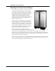
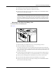
Mounting to the Side of the Battery Case
To mount the sensor on the battery case
See
Figure 6
.
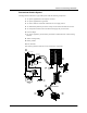
Figure 6. BTS Attached to Battery Case
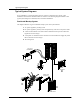
1. Select the battery to be monitored (see step 1 in the preceding procedure).
2. Select a side suitable for attaching the sensor.
The surface where the sensor is to be mounted must be flat and free from reinforcing
ribs or other raised features. As well, this surface must be in direct internal contact with
battery electrolyte, so do not install the sensor on a side near the top of the battery or on
the battery’s top surface.
3. Clean the selected area thoroughly to remove any oil or grease that could prevent the
sensor from adhering to the battery case, and allow the battery case to dry thoroughly.
4. Peel the protective backing from the self-adhesive strip on the rear of the sensor.
5. Press the sensor firmly against the clean side of the battery to fix it in place.
6. Route the sensor cable to the inverter/charger and plug it into the BATTERY TEMP
jack. Secure the cable along its length
.
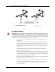
NOTE
In this procedure, you must install the DCcable on the battery terminal first. Then
the sensor is installed on top of the DC cable. This sequence is required to provide
the best connection to the battery and to thereby ensure correct performance of the
sensor.
Adhesive backing allows
for easy mounting on side
of battery.