™ TM500A Battery Status Monitor Installation & Operator’s Guide
About Xantrex Xantrex Technology Inc., is a world-leading supplier of advanced power electronics and controls with products from 50 watt portables to 1 megawatt utility-scale systems for wind, solar, batteries, fuel cells, microturbines, and backup power applications in both grid-connected and stand-alone systems. Xantrex products include inverters, battery chargers, programmable power supplies, and variable speed drives that convert, supply, control, clean, and distribute electrical power.
Table of Contents 1.0 INTRODUCTION ............................................................... 1 The TM500A .......................................................................................... 1 Unpacking and Inspection ..................................................................... 2 TM500A (12/24 Volt) ............................................................................. 2 TM500A - NS (12/24 Volt) .....................................................................
Table of Contents (continued) 4.0 OPERATION ................................................................... 25 Indicators and Controls ....................................................................... 25 Buttons ................................................................................................ 25 Select Button ................................................................................... 25 Reset Button ...........................................................................
IMPORTANT SAFETY INSTRUCTIONS This manual contains important safety instructions that should be followed during the installation and maintenance of this product. To reduce the risk of electrical shock, and to ensure the safe installation and operation of this product, the following safety symbols have been placed throughout this manual to indicate dangerous conditions and important safety instructions. WARNING - A dangerous voltage or condition exists in this area.
BATTERY SAFETY INFORMATION • Always wear eye protection, such as safety glasses, when working with batteries. • Remove all loose jewelry before working with batteries. • Never work alone. Have someone assist you with the installation or be close enough to come to your aid when working with batteries. • NEVER smoke in the vicinity of a battery or generator. • Always connect the batteries first, then connect the cables to the inverter via a DC disconnect switched OFF.
1.
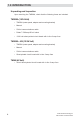
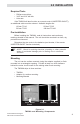
1.0 INTRODUCTION Unpacking and Inspection Upon receiving the TM500A, check that the following items are included.
2.0 INSTALLATION Required Tools • • • Phillips screw driver 3/32" and 3/16" drill bits Hole saw If the TM500A will also function as a remote control (INVERTER ON/OFF), an additional cable must be ordered. Available lengths are: 10 feet–TC/10 50 feet–TC/50 25 feet–TC/25 100 feet–TC/100 Pre-Installation Before installing the TM500A, read all instructions and cautionary markings located in this manual. The unit should be mounted in a clean, dry, protected environment.
2.0 INSTALLATION Surface Mounting • Using the mounting bracket as a template, mark the positions for the screw holes and an area where the cable(s) will feed through. • Drill out the four screws holes (if required) and wire access opening. Use a 3/16" bit if the supplied plastic anchors are used. If placing the screws directly into the backing material, use a 3/32" bit. The wire access hole should be at least 1/2" diameter to allow the connector to pass through.
2.0 INSTALLATION Wire Access Hole Trace Meter Bracket Trace Meter Trace Meter Adaptor Figure 2-2 Surface Mounting the TM500A Using the Adaptor J2 TO INVERTER ONLY J1 TO SHUNT ONLY SPADE LUG Figure 2-3 Communication and Remote Cable Connections © 2001 Xantrex Technology Inc. P/N 973-0012-01-02 Rev.
2.0 INSTALLATION Flush Mounting To flush mount the TM500A , an opening must be cut in the backing material to allow room for the circuit board, wires and connectors. Allow at least one inch depth behind the circuit board for the connectors and wires. • Use the bracket as a template and mark the positions for the screw holes. Mark the open area to be cut out for the circuit board. NOTE: Carefully cut out the circuit board area from the backing material (i.e., wallboard).
2.0 INSTALLATION Area To Be Cut-Out Trace Meter Bracket Trace Meter Figure 2-4 Flush Mounting the TM500A J2 TO INVERTER ONLY J1 TO SHUNT ONLY SPADE LUG Figure 2-5 Communication and Remote Cable Connections © 2001 Xantrex Technology Inc. P/N 973-0012-01-02 Rev.
2.0 INSTALLATION Extended Length Installations If the TM500A is mounted in excess of 100 feet from the inverter, an additional wire (with a spade lugs on both ends) must be connected between the TM500A and shunt spade lugs. This wire acts as a ground reference and ensures the meter will read accurately. Use the following gauge wire for the distance the TM500A is mounted from the inverter.
2.0 INSTALLATION Deltec™ Shunt WARNING: BEFORE WIRING THE SHUNT TO THE BATTERIES, SWITCH THE DC DISCONNECT TO OFF AND/OR REMOVE THE DC FUSE. Mounting/Wiring the Shunt The shunt connects between the inverter and batteries in the negative (–) line (Figure 2-10). • Mount the shunt on or near the battery enclosure close to the negative (–) battery terminal. Use appropriate screws to secure the shunt to the battery enclosure.
2.0 INSTALLATION Mounting Circuit Board to an Existing Shunt Model TM500A - NS is supplied without a shunt and is intended to be wired to an existing shunt. The kit includes two brass 8-32 x 5/8 inch machine screws, two lock-washers and two metal standoffs. NOTE: The shunt must be of the proper type (50 mV/500 amps) and have the necessary threaded screw holes to accommodate the shunt board. • Remove the existing two machine screws (if installed) and hardware from the side of the shunt.
2.0 INSTALLATION Connecting the Shunt Board • Remove the fuse from the in-line fuse holder by rotating the fuse holder cap counterclockwise. • Connect the ring terminal from the fuse holder to the battery’s positive terminal. • Connect the shunt communications cable into the RJ11 jack on the shunt board. This cable can be extended up to 100 feet (30 meters). • Replace the fuse in the fuse holder. Replace the fuse holder cap by pushing and rotating it clockwise.
3.0 CONFIGURATION Setup The TM500A is configured at the factory for monitoring a 12 VDC system. These settings can be changed to meet specific system parameters. The default settings are: % Charge Efficiency 94 % V Voltage (full-charge) 14.4 volts DC A Amperage DC 35 amps Ah Amp Hours Low-Voltage Indicator Recharge Reminder 200 Hours 11.2 volts DC OFF Restoring the Factory Defaults The factory defaults can be restored to their original settings if desired.
3.0 CONFIGURATION Setting Parameters Individual system parameters can be set by the following procedure: 1. Press the SELECT button until the mode selection indicator to be set is illuminated. 2. Press the SELECT and RESET buttons simulataniously. Release both buttons when the LED display flashes. 3. Press and release the RESET button to scroll through the selections (or values) slowly, or hold the RESET button to scroll rapidly. 4.
3.0 CONFIGURATION Setting Parameters (continued) Charge Efficiency % Since batteries are not 100 percent efficient, more energy is required to charge them than can be extracted. Some of this energy is lost in the form of heat and gassing. An efficiency factor of 94 to 98% is typical for lead-acid batteries. Consult the battery manufacturer’s specifications for other battery types. Set this value to 96% for new batteries and 94% (or lower) for batteries already in service. The default setting is 94%.
3.0 CONFIGURATION Setting Parameters (continued) Amp Hours Ah The amp-hour setting should be set to a value equal or lower than the actual amp-hour capacity of the system’s battery bank. Using a number that is lower than the actual amp-hour capacity allows the % Battery State-ofCharge meter to provide a more conservative indication for the use of the batteries to avoid excessively discharging them. Also note the temperature at which the battery capacity is rated.
3.0 CONFIGURATION Setting Parameters (continued) Set Battery Amp-Hour Rating Ah LED Indicates Amp-Hour Function is Selected 280. 1 2 3 4 Figure 3-4 Setting the Amp Hours 16 © 2001 Xantrex Technology Inc. P/N 973-0012-01-02 Rev.
3.
3.0 CONFIGURATION Setting Parameters (continued) (continued) CHARGED Indicator Setup Set Voltage Level 14.4 Voltage LED Illuminates to Indicate the Voltage Function is Selected 1A 4A 2A 3A Figure 3-5 Setting the CHARGED Indicator Voltage Level The fully-charged voltage parameters are now set. To allow the voltage only setting to trigger the fully-charged LED, the amperage setting must be switched OFF. Step B Switching OFF the Amperage Detection 1B.
3.0 CONFIGURATION Setting Parameters (continued) CHARGED Indicator Setup (continued) Trigger on Voltage and Amperage When this mode is selected, the CHARGED indicator LED illuminates when the voltage reaches the programmed level (Step A) and the amperage decreases to the value set in Step B. As batteries charge, their voltage slowly increases and the charging current decreases. Setting these parameters allows the CHARGED indicator LED to illuminate when specified conditions are met.
3.0 CONFIGURATION Setting Parameters (continued) CHARGED Indicator Setup (continued) Set Voltage Level 14.4 Voltage LED Illuminates to Indicate the Voltage Function is Selected 1A 4A 2A 3A Figure 3-7 Setting the CHARGED Indicator Voltage Level Step B Setting the Amperage Trigger Level 1B. Press the SELECT button until the Amperage LED ( A ) is illuminated. 2B. Press the SELECT and RESET buttons simulataniously until the LED display flashes. 3B.
3.0 CONFIGURATION Setting Parameters (continued) CHARGED Indicator Setup (continued) Trigger on Voltage and Time When this mode is selected, the CHARGED indicator LED illuminates when the voltage reaches the programmed level (Step A) and the amperage remains positive for the specified time (Step B). Step A Setting the Fully-Charged Voltage Level 1A. Press the SELECT button until the Voltage LED ( V ) is illuminated. 2A. Press the SELECT and RESET buttons simulataniously until the LED display flashes.
3.0 CONFIGURATION Setting Parameters (continued) CHARGED Indicator Setup Step B (continued) Setting the Time Duration 1B. Press the SELECT button until the Amperage LED ( A ) is illuminated. 2B. Press the SELECT and RESET buttons simulataniously until the LED display flashes. 3B. Press the RESET button until the display reaches the hour settings. These selections are available following the amperage settings.
3.0 CONFIGURATION Setting Parameters (continued) CHARGED Indicator Setup (continued) Charger Considerations There are several different types of chargers (relay, taper or threestage) which can affect the settings and prevent the CHARGE LED from illuminating. Relay Chargers Relay type chargers raise the battery to a set voltage level then shut OFF using only voltage as their parameter. Set the TM500A to the voltage only mode and set the voltage slightly below the charger turnoff setting.
3.0 CONFIGURATION Setting Parameters (continued) Low-Voltage Indicator V The TM500A should be set to trigger on a user specified low DC voltage level. When the battery voltage falls below this level, the VOLTAGE indicator ( V ) flashes approximately once every four seconds. This meter is useful to determine if the batteries are being over-discharged. Refer to the battery manufacturer’s specifications for the proper low-voltage level. A voltage between 10 and 35 volts (10 and 64.
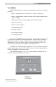
4.0 OPERATION Indicators and Controls The TM500A contains the following controls and indicators. • • • • • Large three-digit LED display Four red mode indicators One green CHARGED indicator One green INVERTER ON/OFF indicator Three pressure sensitive push-buttons The three-digit LED displays alphanumeric messages with a resolution to 0.00. A negative value (–) indicator is positioned to the left of the display.
4.0 OPERATION Indicators and Controls (continued) Basic Meters To display one of the four meters; • • Press the SELECT button until the desired indicator illuminates. The LED display indicates the values for the selected function. Value for selected mode appears in the display Polarity Indicator 12.
4.0 OPERATION Indicators and Controls (continued) Ah (AMP HOURS) When this indicator is illuminated, the LED display shows the total amp hours used since the last time the amp-hour meter was reset. The range is from ±0.00 to ±167,000 amp hours. When the decimal point flashes, multiply the reading by 1000 (i.e., 111. = 111,000). This meter automatically resets to zero approximately one minute after the CHARGED LED remains ON solid (stops flashing).
4.0 OPERATION Indicators and Controls (continued) Data Monitors There are several additional data displays available, accessed by pressing and holding the SELECT button until “dSF” appears in the display. Pressing and releasing the SELECT button alternates between its value, then scrolls to the next menu item. The available data monitor functions are: dSF (Days Since Full) This meter shows the number of days since the batteries were fully charged. The range on this meter is from 0.00 to 655 days.
4.0 OPERATION Indicators and Controls (continued) To access the Data Monitor Function: • Press and hold the SELECT button until dSF appears in the LED display. The display alternates between the data monitor function and its data. • Press the RESET button to display the value for the selected function. • Continue pressing the SELECT button to scroll through all the available displays and their data.
4.0 OPERATION Reminders and Indicators The TM500A features a programmable recharge reminder as well as lowvoltage and charged indicators. Amp-Hour Reminder The Amp-Hour LED can be configured to flash at a specified interval following recharge as a reminder that it is time to charge the batteries. The range is from 1 to 99 days or it can be turned off. When the number of days programmed into this counter is exceeded, the Amp-Hour ( Ah ) LED flashes.
4.0 OPERATION Reminders and Indicators (continued) Low-Voltage Indicator A voltage between 10 and 35 volts (10 and 64.9 volts for 48-volt systems) can be specified to activate the low-voltage alarm. When the battery voltage falls below this level, the voltage indicator ( V ) flashes approximately once every four seconds. To configure this alarm: 1. Press and hold the SELECT button until the dSF message is displayed, then release. 2.
4.0 OPERATION Reminders and Indicators (continued) CHARGED Indicator The CHARGED indicator ( ) can be programmed to flash every four seconds when specified charging criteria are met. This can be voltage only, voltage and current, or voltage and time. When the programmed conditions are met for a minimum of 30 seconds, the CHARGED indicator flashes. The CHARGED indicator stops flashing and remains ON solid when the “charged” conditions are no longer met (i.e.
5.0 TROUBLESHOOTING Symptom LED in INVERTER ON/OFF switch does not light. Voltage displayed on meters is not correct. Possible Cause Solution J2 plug not plugged into TM500A or the inverter. Plug cable into TM500A and Inverter's RC4/RC8 remote control jack. Inverter does not have a compatable Jack. The inverter remote control only operates on models equipped with an RC4/RC8 remote control input. The TM500A voltage is configured above 35.0 volts for a 12- or 24-volt system.
6.0 SERVICE INFORMATION Xantrex Technology Inc., takes great pride in its products and makes every effort to ensure your unit fully meets your independent powering needs. If your product needs repair, contact our Customer Service department at: (360) 435-8826 to obtain an RMA# and shipping information; or, fax this page with the following information to: (360) 474-0616. Or contact the Xantrex Warranty Department at Tracewarranty@traceengineering.com.
7.0 SPECIFICATIONS Specifications Function Range Accuracy Battery Volts 8.0–35 volts 16.0–70 volts ± 0.1 volt ± 0.2 volt Battery Amps 0.1–999 amps ± 1.5% (+ least significant digit) Battery Amps Resolution 0.1 to 99.9 amps ± 0.1 amp 100 to 999 amps ± 1.0 amp Battery Level % Low (< 27.5%) 30–90% FULL (> 92.5%) ~ 2.5% accuracy in 5% increments Current Draw Power Saving Mode All other modes 18 mA maximum 32 mA maximum Amp Hours Battery Capacity -0.
8.0 WARRANTY Limited Warranty Xantrex Technology Inc., warrants its power products against defects in materials and workmanship for a period of two (2) years from the date of purchase, established by proof of purchase or formal warranty registration, and extends this warranty to all purchasers or owners of the product during the warranty period.
Xantrex Technology Inc. 5916 195th Northeast Arlington, WA 98223 U.S.A. t: 360/435.8826 f: 360/435.3945 www.xantrex.com © 2001 Xantrex Technology Inc. P/N 973-0012-01-02 Rev. A 05/01 Printed in U.S.A.