
Battery Status Monitor Operator's Guide TM500A

© 2001 Xantrex Technology Inc. 25
P/N 973-0012-01-02 Rev. A 05/01
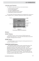
Indicators and Controls
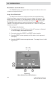
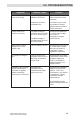
The TM500A contains the following controls and indicators.
• Large three-digit LED display
• Four red mode indicators
• One green CHARGED indicator
• One green INVERTER ON/OFF indicator
• Three pressure sensitive push-buttons
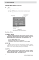
The three-digit LED displays alphanumeric messages with a resolution to
0.00. A negative value (–) indicator is positioned to the left of the display.
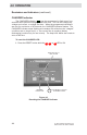
Buttons
SELECT Button
The SELECT button is used to switch the TM500A between the
different meters and modes. One of the LEDs located above the buttons
illuminate, indicating the active function.
RESET Button
The RESET button is used to change the metering parameters and to
reset the CHARGED indicator.
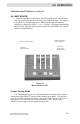
INVERTER ON/OFF Button
The INVERTER ON/OFF button remotely controls the inverter’s ON/
OFF function via the RC4 or RC8 remote control jack. This button
duplicates the function of the inverter’s power switch. The LED
duplicates the indications of the RC8 remote control. Refer to the RC4/
RC8 documentation (supplied with the cable) for LED indications and
modes available (depends on inverter). Remote control cables are
available in 10, 25, 50 and 100 foot lengths. This button/LED does not
function if a remote control cable is not connected or if the inverter does
not support an RC4 or RC8 remote control.
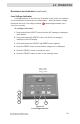
Figure 4-1
Front Panel Controls and Indicators
3-digit
Display
Negative
Mode
Indicators
Select
CHARGED
Indicator
Reset Button
Inverter
ON/OFF
Button
Inverter Mode LED
(on Button)
4.0 OPERATION