i4.
Notice of Copyright Xantrex Link 10 Battery Monitor © November 2002 Xantrex International. All rights reserved. Xantrex is a registered trademark of Xantrex International. © 2002 Xantrex International. All rights reserved. Disclaimer UNLESS SPECIFICALLY AGREED TO IN WRITING, XANTREX TECHNOLOGY INC. (“XANTREX”) (a) MAKES NO WARRANTY AS TO THE ACCURACY, SUFFICIENCY OR SUITABILITY OF ANY TECHNICAL OR OTHER INFORMATION PROVIDED IN ITS MANUALS OR OTHER DOCUMENTATION.
Table of Contents DO NOT INSTALL OR USE THIS PRODUCT UNTIL YOU HAVE READ THE ENTIRE OWNER’S MANUAL. IMPROPER INSTALLATION OF THIS UNIT MAY BE HAZARDOUS AND VOIDS YOUR WARRANTY. Quick Reference Guide..................................................................................................5–6 Introduction.........................................................................................................................7 Battery Basics...............................................................
Basic Wiring Diagram +OSITIVE P EM T VE S I Y T S + EGA N M The Xantrex Link 10 works with flooded or gel lead-acid batteries TE S Y S The 500 A 50 mV shunt senses current in or out of your battery. 2 amp Fuses 1234567 1234567 1234567 1234567 1234567 1234567 Twisted pair wire is used for shunt sensing leads for noise immunity.
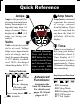
Quick Reference The Light Bar The light bar shows state-of-charge at a glance. Here's what the lights mean: EMPTY FULL Full 80–99%+ 60–79%+ 40–59%+ 20–39%+ 0–19%+ Status Lights Shows what number is being displayed The Button When you press the button, you SELect a numeric display. In normal operation, each press illuminates a status light. The light indicates volts are light indicates being displayed, the amps, indicates amp hours, and indicates time. We’ll explain these terms on the next page.
Quick Reference Amps Amp hours Amps is the present flow of current in or out of your battery. For example, a refrigerator may draw 6.2 amps of current. This is displayed as -06.2 (6.2 amps are being consumed). Amp hours consumed represents the amount of energy removed from the battery. If you run a 10-amp load for one hour, the Link 10 will show -10.0 in the display. Volts Volts is electricity’s potential to do work. Voltage helps assess approximate state-of-charge and to check for proper charging.
Introduction Congratulations! The Xantrex Link 10 is the most advanced (Patents Pending) DC power measurement instrument available. It shows you: Battery State-of-Charge on a multicolor light bar. System voltage accurate to 1/20th of a volt (<20 VDC). System current accurate to 1/10th of an amp (<40 amps). Amp hours removed from, or put into, your battery. Time of operation remaining until recharging is required.
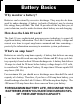
Battery Basics Why monitor a battery? Batteries can be ruined by excessive discharge. They may also be damaged by under-charging. A battery (or bank of batteries) may be storing less energy than you think. The Link 10 provides all the key data you, or your technician, need to make decisions about battery use and charging. How does the Link 10 work? The Link 10 uses sophisticated microprocessor technology to report all significant battery information.
Installation Basic installation of the Link 10 on a 12 or 24 volt system involves only five wires. Because the Link 10 will work on systems up to 500 volts, special high voltage installation techniques are discussed beginning on page 44. You need to read this section if you're working on an electric vehicle or system where more than 50 volts is encountered. If your installation is on a 12 or 24 volt system, let's get to work! Installation Planning First, gather all the tools you'll need for installation.
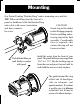
Mounting Our Patent Pending "Ratchet Ring" makes mounting easy and fast. TIP: When installing from the front of a panel or dashboard slide the Ratchet Ring onto cable with correct orientation CAUTION! and then connnect Orient ring so the ratchet the wires. teeth will engage properly. Practice installing and removing ring before final assembly. Considerable force is required—this ensures the ring will not loosen over time.
Removing Removing the Link 10 is the reverse of mounting with a TWIST as shown in the following diagrams. Twist 1/8th turn to unlock teeth. Then pull lock ring straight back as shown below.
Wiring Overview This drawing is for 12 V & 24 V systems. For higher voltages see Prescaler use on page 44. + DC+ - Fuses Shunt Twisted pair cable See Detail page 13 Terminal Strip Connections See Detail page 14 Mounting Page 10 Removing page 11 DC(system ground) INSTALLATION TIP: Use appropriate strain relief to avoid damage to the connector and terminal strip on the rear of the Link 10. TIP: For a neat and professional looking installation use plenty of: * Nylon wire wraps * Wire wrap anchor points.
Shunt & Battery Wires The shunt is the current sensor for the Link 10. Its 500 A, 50 mV rating means that when 500 amps flows through it there is 50 mV generated across it. The millivolt signal is translated into an amps display in the Link 10. For example: a 50 A load would generate 5 mV across the shunt and would be displayed as 50 amps. Caution: in the diagram below, the darker wires represent primary wiring and should be able to carry full battery load current.
Meter Wiring Detail Make the necessary wire connections to the Link 10 as shown in the following diagram: Color code shown for Xantrex 4 twisted pair cable. P/Ns below: P/N 84-2014-00 -25' P/N 84-2015-00 -50' CAUTION Top Rear View Use correct sized screwdriver for terminal screws. Tighten firmly but do not over-tighten to avoid damage DC - Meter Negative (BLACK) Shunt Sense Lead Load Side (GREEN) Shunt Sense Lead Battery Side (ORANGE) Battery Volt Sense (0–50 V DC1)(BLUE) DC + Meter Power (9.
Wire by Wire Check Most failures and problems are due to wiring errors. Please double check the wiring. (Color code shown is for Xantrex wire P/Ns on page 14.) #1 - DC Power (Black Wire). Start at terminal #1 of the Link 10 and follow it to the big bolt on the Load side of the shunt. Do not connect this wire to the small screw terminal with the Green shunt sense lead. #2 Shunt Sense Lead Load Side (Green Wire). This wire connects to the small screw on the Load side of the shunt.
Startup Once you have completed ALL instructions on page 15, insert the voltage sense wire fuse, then the meter power fuse. (BLUE wire fuse first, RED wire fuse last!) The fuse should be in a fuse holder and should be connected in a smooth motion. A "ragged" power-up may cause a meter lockup. Both the bar graph and digital display should come on.
Synchronizing the Link 10 Synchronize the Link 10 to a Full Battery After installing the Link 10, charge the battery until the far right Green LED begins flashing, which indicates the Charged Parameters have been met. Amp hours will have started at 0 and counted up as a positive number. As you begin discharging the battery, the LED will stop flashing and the numeric amp hour display resets to 0. The Link 10 is shipped from the factory assuming a 200 amp hour battery. Your battery may be a different size.
Operation Although the Link 10 is a very sophisticated device, obtaining basic battery information from it is simple. With the unit turned on and the (Volts) LED on, let's learn how to display the four most important DC system parameters. When you touch the button, you are SELecting the display you wish. Each time you touch SEL in normal operation, you will toggle to the next item to the right (volts) goes to (amps) to (amp hours) to (time). i4.25 Now press SEL to bring up these functions.
Reading the Bar Graph Above the digital display are four LEDs. They tell you the battery's stateof-charge at a glance. Four green LEDs means your battery is full. One flashing red light means it is nearly discharged. The table below shows the six different displays indicating battery state-of-charge. Under certain light conditions green may appear yellow.
Using the Buttons Pressing and holding the SET button for three seconds enters the Setup and Advanced Functions mode. The word SEL apppears in the display, prompting you to press the SEL button to choose what function you want to SELect. Pressing SEL chooses a variable or function. The SETUP mode always begins at the (Volts) function. Each press of the SEL button scrolls to the next item. When a variable or function is selected, its LED is on and its present value is displayed.
Setting Battery Capacity The first time you use the Link 10, it assumes you have 200 amp-hour lead acid batteries. If your battery capacity is different you must change the declared battery capacity. Follow these instructions to declare a new capacity: 1) Press and hold the SET button for three seconds to enter SETUP (and Advanced Functions) menu. SEL appears in the display. Press SEL and notice that the green LED is on. light comes on.
The Charged Parameters The Link 10 depends on the Charged Parameters to stay in sync with the battery state-of-charge, to automatically reset to zero, and to automatically calculate the CEF. The default settings are for 12 V lead acid (liquid or gelled) batteries. They have been carefully chosen to work on most systems, including constant voltage and multiple step charging systems. The factory Charged Parameters are 13.2 volts and 2% of battery capacity as a charged current.
Charged Parameters & CEF If you change the Charged Parameters please use the following rules: 1) The Charged Voltage Parameter MUST BE AT LEAST 0.1V BELOW the voltage at which the charging system finishes charging. Example: If your charging system finishes the battery at 13.8 volts, a Charged Voltage Parameter of 14.0 volts will not work. Lower the Charged Voltage Parameter to 13.7 volts or less.
Setting Up Five different displays are available in the Time function. You may select present consumption level, a 4-minute average, a 16-minute, or a 32-minute average, or display the percent of rate compensated capacity remaining. Which method is best for you depends on your installation. Most installations follow the will find four-minute averaging appropriate. To SET UP procedure outlined on page 20. As you press the SET button the following values will appear.
(optional) Temperature Sensor The Link 10 may support an optional two wire temperature sensor. The temperature sensor is activated by turning Advanced Function F16 ON. With F16 ON, F03 shows battery temperature in degrees Celsius. When activated, F03 will continue to display temperature after exiting the Setup mode until one of the two front panel buttons, SET or SEL, is pressed. The limits of the temperature sensor are 0 °C (32 °F) to 99 °C (210 °F).
Puekert's Exponent Peukert's Exponent is a number which describes how battery capacity shrinks as the rate of discharge is increased. The Link 10 uses a number between 1.00 and 1.50 to describe how fast a particular battery will "shrink" when a heavy load is connected. A more complete technical discussion of the Peukert Exponent, and typical value tables is included on pages 39–41. The Peukert Exponent set at the factory, 1.25, will be satisfactory for many liquid cell batteries.
Alarms Two Types of Alarms The Link 10 is equipped with both a visual Power Loss Alarm and a visual Low Battery Alarm. It is important that you understand the difference between these functions. Power Loss Alarm: Shows when power being supplied to the Link 10 has dropped to an unsafe level. Certain display features are turned off as meter power drops below internally set levels.
Reset and Lock In addition to reporting primary system values, the Link 10 is capable of many other front panel functions and will also display important historical battery data. The words below the bar graph display indicate which of these functions you are accessing. To use these functions you must read and understand the following section of this manual. RESET DATA LOCK FUNC Resetting the Link 10 RESET Resets amp hours to zero and resets the Link 10 to factory values.
Historical Data RESET DATA LOCK FUNC Key Battery Data Displayed DATA Key historical battery information is available through this function. Each time the SEL button is pressed while in the DATA mode the next piece of data is displayed. To see DATA, select DATA as previously described. CEF (Displayed as E99): The Charging Efficiency Factor (CEF) is displayed. A display of E99 indicates a 99% CEF. This number sets the rate at which amp hours are counted back up during charging.
Advanced Functions RESET FUNC DATA LOCK FUNC Advanced Functions Allows setup of Advanced Functions. To access the FUNC mode, SELect the FUNC mode as previously described. The letters F0i will appear in the display and the FUNC LED will be lit, indicating you are in the FUNC mode. Continue pressing the SEL button until the function you wish to set up appears. Now press SET until the desired value or mode appears. Repeat this procedure until you have set up all of the desired advanced functions.
Advanced Functions F03 DISPLAY OR SET BATTERY TEMPERATURE If there is no external temp sensor and F16 is OFF (factory default), this function sets ambient battery temperature used to caluculate rate corrected battery capacity which drives the LED bar graph and the Time remaining display. Feature not available on units with serial numbers prior to 05000.
Advanced Functions F06 MANUALLY SET CEF (Not Recommended) Allows manual setup of CEF. Displayed as two digits. Default display A90 indicates automatic CEF recalculation feature active. Returning to A90 from a user CEF turns the automatic CEF feature back on. A user-set CEF will appear as a UXX in the DATA mode. See page 29. DEFAULT: A90 RANGE: 65–99 STEP: 1 F07 SET TEMPERATURE COEFFICIENT Compensates for capacity change with temp. ~ 0.5% Cap/°C. This coefficient must be supplied by the battery manufacturer.
Advanced Functions CAUTION: If you set the discharge floor high, such as 50%, and continue to discharge well beyond this point, you will notice that the bar graph does not "fill up" until you have charged the battery above the discharge floor. In other words, if you set the discharge floor at 50% and discharge 75%, you must recharge back up to the 50% level before your bar graph and time of operation will again give you meaningful information.
Advanced Functions F16 TEMPERATURE SENSOR ON/OFF This function turns the optional external temperature sensor on or off. This feature is only operable when a temperature sensor has been connected between Pin 6 and Pin 8 of the Link 10. To fully understand this feature, please refer to F03 on page 31. Not available prior to Serial Number 005000. DEFAULT: OFF RANGE: ON, OFF F17 LIGHT TEST This function confirms proper operation of the Link 10's front panel display.
Low Battery Alarm Units with serial numbers greater than 005000 allow access to an enhanced Low Battery Alarm feature. To activate this feature, change Function F14 to ON. When F14 is ON, the Link 10 displays a visual alarm when the monitored battery meets either of two conditions: 1) A settable rated compensated (Peukert) amp-hour depth of discharge is exceeded or, 2) Voltage remains below a settable level for 15 seconds or longer.
Alarm Functions Refer to F14 in the Owner's Manual Functions F10, F11, and F12 define operation of the Visual Low Battery Alarm as follows: F11 TURNS ON Low Battery Alarm at a set % of ratecompensated amp hours discharged Amp-Hour Capacity of Battery E.G.
NOTE: The Low Battery Alarm ON and OFF points operate on rate compensated (Peukert) amp hours consumed. Once the alarm is activated, the battery must be charged until Alarm OFF Set Point is reached to turn the alarm off. F12 LOW VOLTAGE ALARM THRESHOLD F12 sets the voltage below which the Low Battery Alarm is activated. But the voltage must remain below this set point for a full 15 seconds before the Low Battery Alarm goes ON.
Optional Alarm Switch Special versions of the Link 10 are available, for additional charge, which include a solid state Alarm Switch to ground via rear panel terminal strip Pin #7. This option is used in a variety of settings such as lift pump lock out on fork lifts, two wire generator start/stop, audible low battery alarms, and charge controllers. The additional circuitry of the switch may not be retrofitted to the Link 10 in the field. It must be included at the time of manufacture.
Peukert's Equation Peukert's Equation describes the effect of different discharge rates on battery capacity. As the discharge rate increases, the available battery capacity decreases. The table and examples on the following page illustrate this effect and how to use the table to estimate the exponent "n". The tables on pages 40 and 41 have typical values of "n" for common batteries.
Peukert's Equation The table below may be used to understand the effect of high rates of discharge on available battery capacity. It may also be used to estimate the exponent "n" for a battery after a single discharge test. The table is based on a 100-Ah battery but may be used for any capacity battery by using an appropriately scaled current. See the examples below: EXPONENT PERCENTAGE OF AVAILABLE CAPACITY FROM A 100 Ah BATTERY AT DIFFERENT DISCHARGE RATES USING DIFFERENT PEUKERT'S EXPONENTS n 1 1.1 1.
Peukert's Exponent Typical Values for Peukert's Exponent "n" This table contains values for the exponent "n" for various batteries and manufacturers. They are calculated from the 20-hour rating and the Reserve Minutes @ 25 A as supplied by the manufacturer. They should be considered only a guide for selecting "n." Prevailer & SeaGel Batteries Model Volts Res. Min. 20-Hr. rating "n" 8GGC 8GU1 8GU24 8GU27 8GU30H 84D 8G8D 6 12 12 12 12 12 12 375 43 130 167 188 388 500 180 43 70 86 95 180 225 1.14 1.20 1.
Peukert's Exponent Surrette and Rolls Batteries Model Volts Res. Min. 20-Hr. rating "n" EHG-208 EIG-225 EIG-262 24/90 27/12M 30H/108 HT/4D HT/8D 6 345 208 6 350 225 6 395 262 12 165 90 12 190 112 12 230 108 12 348 170 12 450 221 *Use Max allowed "n" of 1.50 1.42 1.54* 1.72* 1.16 1.23 1.08 1.15 1.20 Example of using Reserve Minutes @ 25 amps and the 20-hour rate to calculate "n". First convert Reserve Minutes to hours, then find the discharge current at for the 20-hour rating.
Troubleshooting Problem Suggestion No lights or display Check Power Connections Reset meter (page 28) Check Lock is not invoked Reset meter (page 28) Check Battery Capacity (page 21) Check Temperature Coefficient (page 32) Check Peukert Exponent (page 26) Clean front panel photo-sensor (Between A and Ah lights) Current Shunt leads reversed (page 13) Corrosion or loose wires. Loosen and reconnect all rear panel connections. Check voltage sense and shunt wiring at battery location.
Options & Versions User-installable OPTIONS available include: Prescalers: Extend the voltage range covered by the Link 10 to either 0–100 V (Xantrex P/N 84-6000-0) or 0–500 V (Xantrex P/N 84-6000-05). Temperature Sensor: Reports battery temperature in Degrees Celsius (Xantrex P/N 84-2024-00) All other options must be installed at the time the Link 10 is manufactured, as additional circuitry is involved.
High Voltage Prescaler CAUTION! 1. 2. Installation of the Prescaler Option involves work with potentially fatal voltages. NEVER work alone—have at least one person present who can render assistance and CPR in the event of an accident. If you have any doubt about your qualifications to work on a high-voltage system, DON'T DO IT! When working with any DC system, even so-called ungrounded ("floating") systems with no planned chassis connection, disconnect the negative battery terminal first.
Electric Vehicles (EVs) The Link 10 is the ideal energy meter for EV instrumentation. It not only provides volts, amps, amp hours and time remaining, it adds two important bonuses: kilowatt hours and optional serial computer output. If you design or work with electric vehicles or battery-powered equipment of any type, you should realize that kilowatt hours are a more accurate measure of energy used than are amp hours. Here's why: The term "amp hour" defines current (amps) multiplied by time (hours).
EV Installations The negative of the Link 10's power supply must be common to the negative of the battery (motive pack) which you are measuring. This may pose difficulty if your electric vehicle uses an "unbonded" or "floating" (no connection to the chassis) motive pack and a "bonded" (connected to the chassis) accessory battery. In these instances, the use of a DC-DC converter, or a separate battery with a common negative with the motive battery is required.
Lift Truck Installations Installation of the Link 10 in lift trucks, which have the motive pack bonded to the chassis and also have a 12 V accessory battery bonded to the chassis, may use the diagram below for proper wiring of the appropriate Prescaler. The 0–100 V Prescaler is used where system voltage does not exceed 100 V at any time, including during onboard charging. In any other instance, a 500 V Prescaler must be used.
(optional) Serial Port, RS-232 The Link 10 may be equipped to transmit serial communications data to a personal computer or a data logging device. When equipped with the optional RS-232 port, the Link 10 will transmit a data message once a second.
High Voltage Notes HOW TO SET VOLTAGE SCALING WHEN USING A HIGH VOLTAGE PRESCALER F13 SET VOLTAGE SCALING Sets proper voltage scaling when used with an external Voltage Prescaler. NOTE: If you use a Prescaler, you need to change the Charged Voltage to an appropriate value for your application. See "Charged Parameters" on pages 22 and 23. DEFAULT: 0= 0–50 V.
EC Declaration of Conformity CE Manufacturer: XANTREX TECHNOLOGY, INC. Address: Xantrex Technology, Inc. 8999 Nelson Way Burnaby, BC Canada V5A 4B5 Herewith declares that the Xantrex Link 10 is in conformity with the provision of the EEC Directive EMC 89/336/EEC and amendments 92/31/EEC, 93/68/EEC.
Limited Warranty What does this warranty cover? This Limited Warranty is provided by Xantrex Technology, Inc. (“Xantrex”) and covers defects in workmanship and materials in your Xantrex Link 10 Battery Monitor. This warranty lasts for a Warranty Period of 12 months from the date of purchase at point of sale to you, the original end user customer. This Limited Warranty is transferable to subsequent owners but only for the unexpired portion of the Warranty Period.
Limited Warranty IN NO EVENT WILL XANTREX BE LIABLE FOR ANY SPECIAL, DIRECT, INDIRECT, INCIDENTAL OR CONSEQUENTIAL DAMAGES, LOSSES, COSTS OR EXPENSES HOWEVER ARISING WHETHER IN CONTRACT OR TORT INCLUDING WITHOUT RESTRICTION ANY ECONOMIC LOSSES OF ANY KIND, ANY LOSS OR DAMAGE TO PROPERTY, ANY PERSONAL INJURY, ANY DAMAGE OR INJURY ARISING FROM OR AS A RESULT OF MISUSE OR ABUSE, OR THE INCORRECT INSTALLATION, INTEGRATION OR OPERATION OF THE PRODUCT.
RS-232 Warning When using an RS-232-equipped version of the Link 10 in an electric vehicle which has a floating motive battery negative, remember that Pin #5 of the DB-9 connector coming out of the back of the Link 10 is connected to the motive battery negative. This normally causes no problem when used with laptop computers. However, if you plug the DB-9 RS-232 output into a computer with a metal chassis then motive battery negative will be connected to the chassis of the computer.
Software History Software Enhancement Rev. E 1.5 The Link 10 now includes the following additional functions: F02 - ENHANCED SLEEP MODES DEFAULT: ON Range: ON, OFF, AUTOMATIC When the Sleep Mode is ON, the Link 10's numeric display turns off after 10 minutes in order to reduce power consumption. Pressing either SET or SEL buttons returns the numeric display to operation. When the Sleep Mode is OFF, the numeric display stays on at all times.
Software Addendum Software Enhancement This version of the Link 10 includes special software. F18 - SMALL BATTERY SENSING DEFAULT: OFF Range: OFF, ON When this function is OFF, the meter operates as described elsewhere in this manual. When this function is ON, the amp-hour capacity range allows capacities as low as 2 amp-hours to be declared.
Index Advanced Functions, 30–34 Reading the Bar Graph, 19 Battery Basics, 8 Removing, 11 CE Declaration of Conformity, 51 Reset and Lock, 28 Charge Efficiency Factor, 23 Serial Port, RS-232 (optional), 49 Setting Battery Capacity, 21 Charged Parameters, 22–23 High Voltage Notes, 50 Setting Peukert's Exponent, 26 Historical Data, 29 Setting Up t , 24 Installation (General), 9–15 Shunt & Battery Wires, 13 Introduction, 7 Specifications, 59 Low Battery Alarm, 27, 35–38 Startup, 16 Low Voltage, 27
Specifications Voltage: For 12 V–24 V systems. Optional Prescalers extend voltage range. Standard Model: Two Auto-ranges: 0 to 19.95 V (0.05 V resolution) V 20.0 to 50.0 V (0.1 V resolution) Optional Prescalers: 0–100 V, 0–500 V (Used with standard model) Amperage: Low Range: + 0–40.0 amps (0.1 amp resolution) A High Range: + 500 amps (1 amp resolution) Amp-hours: Low Range: +0–199.9 amp hours (0.
Xantrex Technology Inc. Toll free 1 800 670 0707 Direct 1 604 422 2777 Fax 1 604 420 2145 CustomerService@xantrex.com www.xantrex.com 445-0195-01-01 Rev. 1 Printed in the U.S.A.