OPERATION and MAINTENANCE MANUAL for MODEL PV-30208 30 kW Grid-Tied Photovoltaic Inverter Document #151315 Revision E November 17, 2003 IMPORTANT SAFETY INSTRUCTIONS SAVE THESE INSTRUCTIONS - THIS MANUAL CONTAINS IMPORTANT INSTRUCTIONS FOR XANTREX TECHNOLOGY MODEL PV-30208 GRID TIED PHOTOVOLTAIC INVERTER THAT SHALL BE FOLLOWED DURING INSTALLATION AND MAINTENANCE OF THE PV30208. Xantrex Technology Inc. 161-G SOUTH VASCO ROAD Livermore, CA 94551 (925) 245-5400 Copyright 2003, Xantrex Technology Inc.
Table of Contents Product Description ................................................ Section 1 Introduction ............................................................................. 1-1 Major Components ................................................................. 1-1 Interconnection Standards Compliance ..................................... 1-2 Specifications .......................................................................... 1-3 Equipment Symbol ...........................................
SECTION 1 PRODUCT DESCRIPTION INTRODUCTION The Xantrex Technology Model PV-30208 is a 30 kW Grid Tied Photovoltaic Inverter. It utilizes advanced power electronics to allow the interface of a photovoltaic array with an utility grid. The PV30208 is a highly integrated assembly, consisting of an inverter bridge and associated control electronics. The PV-30208 control software provides for complete overall system control with the required protective and safety features.
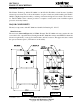
SECTION 1 PRODUCT DESCRIPTION CAUTION The fuses within the PV-30208 are intended for protecting the PV-30208 control circuitry only. They are not intended to provide protection for the PV array or external cabling. Matrix Bus Board The PV-30208 design makes use of a fully integrated matrix bus board as shown in Figure 1-2. The bus board assembly is mounted to an aluminum extrusion heatsink, which is mounted between the upper and lower enclosures.
SECTION 1 PRODUCT DESCRIPTION SPECIFICATIONS The PV-30208 has been designed for photovoltaic power systems, which operate within the following specifications. Application of the PV-30208 in a manner inconsistent with these specifications may cause damage to the PV-30208 and other system components, and is a violation of the terms of the warranty. Nominal AC Line Voltage 208 VAC, +10% - 12% Maximum AC Line Current 94 ARMS (at low line voltage) Nominal Line Frequency 60 Hz, +0.5 Hz - 0.
SECTION 2 SAFETY SAFETY FEATURES WARNING The PV-30208 enclosure contains exposed high voltage conductors. The upper enclosure access panel should remain closed, except during maintenance or testing. These servicing instructions are for use by qualified personnel only. To reduce the risk of electric shock, do not perform any servicing other than that specified in the operating instructions unless you are qualified to do so.
SECTION 2 SAFETY ISOLATION PROCEDURE Anti Island Protection A digital phase-shift-loop (PSL) circuit is implemented in the DSP inverter controller to prevent “Islanding” of the PV-30208. The DSP continuously makes minor adjustments to the power factor phase angle above and below unity. In the event of a utility outage, these adjustments destabilize the feedback between the inverter and the remaining load, resulting in an over/under frequency or voltage condition.
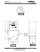
SECTION 3 INSTALLATION AND INITIAL TURN-ON ISOLATION TRANSFORMER REQUIREMENTS The PV-30208 UL1741 certification requires the use of a Xantrex Technology specified 30 kVA WYE/ WYE isolation transformer between the inverter AC output and the utility interconnection (see Appendix in Section 7 for transformer dimensions and specifications). This custom 30 kVA isolation transformer is not part of the 30 kVA inverter, but can be ordered as a separate item.
SECTION 3 INSTALLATION AND INITIAL TURN-ON The following table shows acceptable wire gauges to be connected to the PV-30208 AC and DC inputs. Wire Gauge Table Termination Wire Range AWG Distribution Block (AC) 2/0- #2 Distribution Block (DC) 2/0- #2 INSTALLATION INSTRUCTIONS CAUTION All wiring methods shall be in accordance with the National Electrical Code ANSI/ NFPA 70.
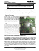
SECTION 3 INSTALLATION AND INITIAL TURN-ON Figure 3-1 Lift Here Cable Entry Access Panel (Both Sides) Figure 3-3 Figure 3-2 DOCUMENT: 151315 PV-30208 Photovoltaic Inverter Operation and Maintenance Manual Copyright 2003, Xantrex Technology Inc.
SECTION 3 INSTALLATION AND INITIAL TURN-ON Array Grounding NEC 690-41/42 requires the PV array to be earth grounded. The PV-30208 is shipped with a ground bond for installation between the pv negative terminal block to the pv safety ground terminal block. The PV-30208 chassis is also bonded to the PV safety ground terminal block. This ground bond is clearly marked with a warning label which must be read before installation.
SECTION 3 INSTALLATION AND INITIAL TURN-ON The following wires for connecting the PV-30208 to external devices are not provided by Xantrex Technology: (See wiring diagram on page 3-6.) • • • • • • • • 3-Phase 208 VAC inverter output to terminals of the 208 VAC primary side of isolation transformer. The neutral must be left floating. Ground loops will exist when the inverter starts switching, which will cause the inverter to shut down due to phase over-currents and will result in damage to the PV-30208.
DOCUMENT: 151315 PV-30208 Photovoltaic Inverter Operation and Maintenance Manual Copyright 2003, Xantrex Technology Inc.
SECTION 3 INSTALLATION AND INITIAL TURN-ON INITIAL TURN ON PROCEDURE The following must be performed by an approved Technician: The following procedures are intended to verify correct installation and proper operation of the PV30208. These steps are to be followed sequentially. Do not continue if any of the steps or results are unclear. Refer to Section 4 for a detailed description of system operation. Refer to Section 5 for fault condition descriptions and troubleshooting.
SECTION 3 INSTALLATION AND INITIAL TURN-ON • • • • • • • • • • • • • • • • Carefully measure VDC at the PV disconnect switch. The value should be the same as at the PV array string disconnect device. It should also be positive. Close the PV disconnect switch (if present). Carefully measure VDC across TBDC+ and TBDC- (PV +/-) terminal block. The value should be the same as at the PV array string disconnect device. It should also be positive. Open the PV disconnect switch.
SECTION 4 OPERATION DESCRIPTION OF SYSTEM OPERATION Overview The PV-30208 is a fully automated grid-tied photovoltaic inverter. Manual interaction or control of the inverter is necessary only in the event of a system fault. The following conditions govern PV-30208 operation: • • • • Stable utility voltage and frequency must be present for all states of operation. Fault states are automatic from any state of operation. A fault will cause the PV-30208 to immediately stop processing all power.
SECTION 4 OPERATION OPERATION FEATURES Automatic Phase Sequence Detection During system power-up, the PV-30208 detects the phase rotation of the three-phase utility voltage as seen at the inverter output terminals. The control software then determines the proper switching sequence for the output power stage. It is not necessary to maintain a particular phase sequence convention between the inverter and the utility point of interconnection.
SECTION 4 OPERATION Ground Fault Detection The PV-30208 is capable of detecting PV array ground fault current. To enable this feature, a wire must be installed between ground and the desired ground reference point on the PV array. For bipolar PV array configurations, the ground wire must be connected between the PV array neutral point and TBNEUT terminal block.
SECTION 4 OPERATION Current Imbalance Detection In the event of phase-to-phase current imbalance of greater than 20% between phases, the inverter will execute an orderly shutdown, and annunciate a fault at the operator interface. See Section 5, Troubleshooting, for further information on this fault condition. DC Overvoltage Detection In the event of DC voltage greater than 600Vdc, the PV-30208 will execute an orderly shutdown and annunciate a fault to the operator interface.
SECTION 4 OPERATION OPERATOR INTERFACE The PV-30208 is equipped with an Liquid Crystal Display. The display consists of 4 text lines containing the following information: • Line 1: System Status - The current operating state of the inverter. • Line 2: DC Current or Fault Descriptions - This line reports the DC current (amps). If the PV30208 is faulted, this line will report a description of the fault condition. • Line 3: Bus Voltage or Fault Code - This line reports the Bus Voltage, in volts.
SECTION 4 OPERATION System Fault System Sleep Test System Stop System Shutdown EXAMPLE OF NORMAL SYSTEM OPERATION Upon initial application of AC voltage, the LCD located on upper enclosure will display ‘Shutdown’ for approximately 15 seconds. Once the system has finished initializing, the PV-30208 will remain in standby until adequate PV voltage is available.
SECTION 4 OPERATION SYSTEM OPERATING PARAMETERS The PV-30208 contains a number of system operating parameters which may be field adjusted using an optional graphical user interface program (contact Xantrex Technology for further information). All operating parameters have been set at the factory during system test based upon prior experience with various PV arrays, or to be in compliance with UL1741.
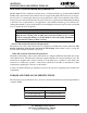
SECTION 4 OPERATION Parame te r De s cription Volts Max Maximum Allowable Utility Voltage Cycle Max High Line Voltage Timer, Cycles Volts Min Minimum Allowable Utility Voltage Cycles Min Low Line Voltage Timer, Cycles Freq Max Delta Us e r Se ttable Range Factory Pas s word Re s olution De fault Prote cte d Se tting 166.4- 249.6 0.1 V 228.8 * 2- 120 1 Cycle 115 * 166.4- 249.6 0.1 V 183.0 * 2- 120 1 Cycle 115 * High Line Frequency Level - 3.0- 3.0 0.1 Hz 0.
SECTION 4 OPERATION Parame te r Earth_Volts_Max De s cription Maximum Earth Voltage Us e r Se ttable Range 0.0- 300.0 Factory Pas s word Re s olution De fault Prote cte d Se tting 01 VDC 0=Off, 1=Up/Down Freq, 2=Up Freq, 3=Down Freq 50 1 Anti_Island_Method Anti- Island Method PPT_Ramp_Time PPT Ramp Time 1- 60 1 Second 20 PPT_V_Step PPT Voltage Step 0 . 1- 10 . 0 0.
SECTION 5 TROUBLESHOOTING GENERAL In the event of a fault, the PV-30208 will annunciate the condition at the operator interface. The PV30208 will execute an orderly shutdown and remain faulted until the fault is cleared (manually or automatically). In general, the operator should respond to any PV-30208 fault as follows: 1. The source of the fault should be sought by referring to the following chart. 2. Rectify the fault condition and attempt to clear the fault by cycling the on/off switch. 3.
SECTION 5 TROUBLESHOOTING FAULT DESCRIPTIONS AND TROUBLESHOOTING FAULT DESCRIPTIONS Fault De s cription Fault Code (LCD) IPM Device Fault A+ 0x0001 IPM Device Fault A- 0x0002 IPM Device Fault B+ 0x0004 IPM Device Fault B- 0x0008 IPM Device Fault C+ 0x0010 IPM Device Fault C- 0x0020 AC Line Under Voltage 0x0100 AC Line Over Voltage 0x0200 AC Line Under Frequency 0x0400 AC Line Over Frequency 0x0800 Ground Current Fault 0x8000 DC Bus Over Voltage 0x4000 CT Offset Fault 80000 Curre
SECTION 5 TROUBLESHOOTING when the contactor closes. Carefully check voltage at the K1-N.O. aux. contact to the ground bus when the contactor is closed. (See schematic in Section 7). (2) AC Line Voltage Low Fault (0x0100) The utility AC voltage fell below the minimum programmed limit. There are two levels of response to low line voltage conditions. The first level of response is set to 183.0 VAC with a time delay of 2 seconds. By default, the second level is set to 104 VAC with a time delay of less than 0.
SECTION 5 TROUBLESHOOTING This fault is auto-resetting. The unit will automatically restart after line has stabilized within normal limits for 5 minutes. Frequency setpoints may be modified via the operator interface program. Utility protection setpoints may only be adjusted by trained personnel with approval by both the local utility and the equipment owner. (5) AC Line Over Frequency Fault (0x0800) The AC frequency exceeded the maximum-programmed limit. This limit is set to 60.
SECTION 5 TROUBLESHOOTING • • • • • • processed. Check +/- VDC power supply outputs. Check control wire harness integrity (Refer to the system schematic in Section 7). Check CT harness for damage. Check CT harness +/-15VDC at CT. Check CT output voltage (mV) with reference to ground. Replace CT showing high output voltage offset. (9) Current Imbalance Fault (0x10000) The PV-30208 has determined that there is an excessive phase-to-phase current imbalance, while the system is operating.
SECTION 6 PREVENTATIVE MAINTENANCE PERIODIC MAINTENANCE Xantrex Technology recommends that the following preventative maintenance be carried out on the PV-30208: Monthly intervals or as required: Aluminum Extrusion Heatsink Accumulation of dirt and debris on the aluminum extrusion heatsink and fan shroud will decrease the ability to transfer heat, which can cause the PV-30208 to shutdown on over-temperature alarms. Inspect the aluminum extrusion heatsink and fan shroud for accumulation of dirt and debris.
SECTION 6 PREVENTATIVE MAINTENANCE WARNING The terminals of the PV input may be energized if the arrays are energized. In addition, allow 5 minutes for all capacitors within the enclosure to discharge after shutting down the PV-30208. 1. 2. 3. 4. 5. Turn the on/off switch to the off position. Open the PV array disconnect switch (if present). Open the AC disconnect (if present). Open the isolation transformer circuit breaker.
SECTION 7 DRAWINGS AND PARTS LIST DRAWINGS LIST 151384 : Schematic, System, Grid Tied Inverter, PV-30208 151316 : Envelope Drawing, Grid Tied Inverter, PV-30208 151317 : Assembly, Main Enclosure, Control Components, 30 kVA, PV-30208 151723 : Transformer, 30 kVA, 3-Pole, 60 Hz, 98% Efficient, 208Y/120 or 480Y/277 WARRANTY AND CERTIFICATIONS Xantrex Inverter Warranty Registration Underwriters Laboratories Compliance Of Standard UL1741 OPTIONAL ACCESSORIES For details and specifications on Xantrex Technology
Xantrex Technology Inc. PV-30208 Photovoltaic Inverter Major Parts List Assembly Description: Main Enclosure, Control Components, PV-30208 Xantrex Technology Inc.
Xantrex Technology, Inc. Distributed Power Markets 161G South Vasco Road Livermore, CA 94550 USA Phone +1 925.245.5400 Fax +1 925.245.1022 XANTREX PV SERIES LIMITED WARRANTY AND REGISTRATION Xantrex Technology warrants all equipment supplied to Customer under this purchase order against defects in workmanship and material for a period of (12) twelve months from delivery, provided that the equipment has been operated and maintained in accordance with the service manual provided with the equipment.