X-25 Installation Manual XBLUE Networks Copyright©
Notifications and Conventions Hearing Aid Compatibility All telephone endpoints are hearing aid compatible, as defined in section 68.316 of Part 68 FCC Rules and Regulations. UL/CSA Safety Compliance This equipment has met all safety requires and found to be in compliance with the Underwriters Laboratories (UL) 60950-1 Documentation Disclosure The information contained in this document is subject to change without notice and may not be construed as a commitment by XBLUE Networks, LLC.
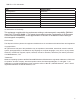
TABLE 1.1 FCC Information Item Specification FCC Registration D6XIG7600 FCC US D6XKH00BIG7600 IC 3187A-IG7600 Ringer Equivalence 0.5B Networks Address Signalling E Service Order Code 9.0Y Facility Interface Code 02LS2 Required Network Interface RJ11, RJ14 & RJ45 CE Declaration of Conformity This equipment complies with the requirements relating to electromagnetic compatibility, EN55022 class B for ITE and EN 50082-1.
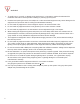
WARNING 1. To avoid injury to yourself, or damage to the equipment, it is important to read and understand the installation instructions carefully before installing or powering up the system. 2. Unauthorized opening the server, the telephone or other associated equipment may cause damage to the equipment and yourself as well as voiding the manufactures warranty. 3. Do not install any equipment in direct sunlight or expose it to excessive heat or fire. 4.
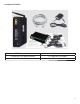
Contents of the Box X-25 Telephone Server 47-9005 (8) Port Telephone Switch Quick Installation Guide 6′ Ethernet Cable (4) Telephone Line Cables Power Supply 5
About This manual This manual was written to assist with the installation of the XBLUE X-25 System and is best used as a reference tool. We have done our best to describe all products and features as they actually work, but we apologize if the manual is incorrect in areas. The headings in this manual are used to identify where in the system you are, and what parameters are programmed within the section.
Table of Contents 1 Notifications and Conventions ........................................................................................ 2 Hearing Aid Compatibility ............................................................................................................................ 2 UL/CSA Safety Compliance ......................................................................................................................... 2 Documentation Disclosure ...........................................
Busy Lamp Field (BLF) .............................................................................................................................. 27 Call Abandon ............................................................................................................................................. 27 Call Forward .............................................................................................................................................. 28 Busy Call Forward .........................
Night Service ............................................................................................................................................. 33 Numbering Plan ......................................................................................................................................... 33 Off Hook Preference .................................................................................................................................. 33 One Touch Record ..........................
Call Forward - External .......................................................................................................................................... 44 Call Forward - Call Forking ........................................................................................................................ 45 Call Forward - Follow Me ........................................................................................................................... 46 Call Park ...............................
Wireless - MAC Filtering ........................................................................................................................... 79 Wireless Bridge ......................................................................................................................................... 80 Wireless Advanced .................................................................................................................................... 82 Station Info ....................................
Access Control ........................................................................................................................................119 Service Port ..........................................................................................................................................................119 Services ...............................................................................................................................................................
Introduction The X-25 Small Business System is a full featured Session Initiated Protocol (SIP) Voice over Internet Protocol (VoIP) telephone system and gateway, with an integrated automated attendant and voice mail system, which will handle up to four simultaneous calls, and equipped with four FXO Ports to accommodate four standard (PSTN) telephone lines, and one FXS Port, to accommodate one single line (analog) telephone for cordless, corded, conference room telephones or FAX machine.
LAN vs WAN The X-25 comes with one Local Area Network (LAN) and one Wide Area Network (WAN) port allowing it be installed as either a client or a server. The LAN port is only used when communicating to devices within the same local area, whereas the WAN can be used to communicate to local devices as well as devices over the Internet. LAN In reality a “Network” is nothing more than a network of wires, or Wireless Protocol, which is used to join two or more computing devices.
The X-25can be installed in several different ways. As a client on your existing data network, as a standalone telephone system, or as the main data network. Client on your existing network When connecting the X-25 to your existing network, use only the Wide Area Network (WAN). The Cloud ISP Router Switch In this case only the WAN port is used of your X-25 is connected and it is considered a “Client” on your existing Local Area Network.
Remote Telephones - When connecting remote telephones to your X-25, it must be the “Edge Device”, which is defined as a demarcation device between the external Internet Service Provider’s (ISP) IP Address and your internal LAN IP Address. This also requires a static “Class A or B” IP Address. There are two ways of installing the X-25 as the edge device, one is to only use the WAN port and the other is to use both the WAN and the LAN ports.
What does that say? When connecting remote users the Internet Service Provider (ISP) must program their DSL/Cable modem to be a “Bridge” or a “Concurrent Bride” allowing the X-25 to join the Internet directly through your ISP’s DSL/Cable modem.
System Capacities Table 2.1 Maximum Configuration PSTN Telephone Lines 4 Lines 8 Telephone Lines SIP (Cloud) Trunks (Telephone Lines) 4 SIP Trunks SIP Extensions Single Line (Analog) Telephone Extensions 16 Extensions 1 17 Extensions (16 SIP and Cellular and 1 Analog) Table 2.2 Physical System capacities Capacity 1 1 1 4 1 Interface LAN WAN FXS FXO 802.
LED Lights on the X-25 Table 2.
Notes: 20
System Specifications Table 3.1 System Specification Feature Description Main Processor Processor SDRAM Processor Flash ROM Supplementary Processor System Flash (Voice Mail) Giga WAN PHY Chip Standards Ports Buttons Ports LED’s EMI/EMC 400 MHz Dual Core MIPS Processor Broadcom BCM6369 External 64 MB External 16 MB 1x DSP Mindspeed M82351 512 MB Broadcom BCM5481 IEEE 802.11 a/b/g/n, IEEE 802.
Table 3.
Protocol TCP Documentation RFC 793 Telnet RFC 2946 TFTP RFC 2349 UDP RFC 768 CLIP Description Transmission Control Protocol provides the reliability that Internet Protocol (IP) does not, making it suitable for applications such as File Transfer and emails. Telnet is a reliable connection-oriented transport protocol, which is Client/ Server Based. At default Telnet uses Port 23. Trivial File Transfer Protocol is a very basic and simple protocol, which is loosely based on the FTP protocol.
Signalling Documentation Description ToS RFC 791, 1060, 1122, 1123, 1195, 1247, 1248, 1349, 2474, 3168 The type of service octet is part of the Internet Protocol header that specifies the priority of the attached datagram (message). DTMF RFC 4733 AF Class RFC 2597 EC RFC 3246 Dual Tone Multi-Frequency Tones - also known as touch tone® - Defined protocol for transmission of DTMF tones transmitted over a packetswitched network. One part of QoS, is Assured Forwarding Classes.
Feature Description Table 4.
Access Control - Browser For security, the X-25 is password protected with a programmable port, making it more secure. There are three different password levels; Administrator and Support, which both give you access to all aspects of programming and user which allows you to view configuration settings and statistics but not modify parameters. Notes: Only one administrator can log into the X-25 at one time. Additional attempts to enter the system will be Denied.
Automatic Daylight Savings (NTP) When the X-25 system is connected to the Internet it will automatically synchronize the date and time using Network Time Protocol (NTP). Therefore, when the time changes for daylight savings, the system will automatically change. Automatic Hold Automatic hold allows extension users to press a preprogrammed extension button known as direct station select (DSS) to announce a call without pressing hold first. The telephone line call is automatically placed on hold.
Call Forward At default, all extensions are forwarded to voicemail. However, they can also use several other types of call forwarding such as; busy, direct, do not disturb, follow me, call forking, and Remote (External). These can be programmed using the web interface, which is easier, or by dialing the call forward code found on page 43. Busy Call Forward Busy call forward, forwards all incoming calls to the forwarded destination only when the extension is busy.
Call Pickup Group Any extension SIP telephone endpoint can dial star “ * ” to pick up a telephone line that is ringing at a different extension. If multiple telephone lines are ringing the oldest ringing line will be accessed. Call Restriction When making a telephone line call all digits dialed will be compared to the telephone’s Class of Service and Restriction Table.
Call Waiting While on a call with the X-2020 telephone you can be alerted to a second call. In the display, you will see the second call, and have the ability to pick up the call or let it forward to voice mail. This feature will not work if your telephone is busy forwarded. Caller ID The system is equipped to receive caller ID (requires a subscription) from the telephone line provider and will, at default, pass the information to a ringing telephone (SIP or Analog) extension.
Distinctive Ringing Telephone Line Each Telephone Line (PSTN or SIP Trunk) can be programmed to ring with one of eleven different ring tones. Extension Each X-2020 telephone endpoint can be programmed to ring with one of eleven different ring tones. When a telephone line rings at an extension that has set distinctive ring, the telephone line ring tone will override the station distinctive ringing. Domain Name Server (DNS) A domain name server is a “Phonebook” for the Internet.
Flexible Numbering Plan The X-25 is preprogrammed with a default numbering plan which you may customize. Some features show “Start...”, which means that the number shown is the first number of the sequence. For example, Start PSTN Line Number 701, which is line 1, lines 2 - 4 will be 702, 703 and 704. When changing the numbering plan it is important to remember that the numbers entered cannot conflict with each other or the numbers entered in the emergency call table, such as 911.
Meet me page Meet me page allows an extension user to dial a code from any extension within the system and be connected to the person that just completed a page. Once the call is established the paging port is released and the two parties will converse privately. Message Waiting Indication (MWI) Whenever a new voice mail message is left for an X-2020 telephone the light bar above the LCD display will flash and the display will update to indicate that there is a new voicemail message.
Outside Calls Once Authenticated, and X-2020 telephone can dial without going off hook, pressing the speaker button, or accessing a telephone line. In addition, the user can press the softkey under “Backsp” to delete an incorrectly dialed telephone number. Once the “Dial Time-out” timer expires (default 5 seconds), or the user press “Dial” under the display or the center navigation key (Check) the call is sent to the system for processing.
Redial Also known as Last Number Redial or Call Log, allows you to select previously dialed, received or missed telephone numbers by selecting them from a list stored on the X-2020 telephone. Registration Server The system is equipped to act like a registrar server for both telephone end points and SIP trunks, which eliminates any possibility of a numbering conflict. Remote Management The system combines both Proxy and Registrar servers in its application.
System Time and Date When connected to the Internet the system uses Network Time Protocol (NTP) to synchronize the time and date. In addition, the date and time can be set manually. Time and Date in Display The first line on the LCD of the idle X-2020 telephone shows the date and time. The time format can be changed from the default, “USA Time 12 Hour” to “USA 24 Hour” or “European 12 and 24 Hour” format.
UCD Reroute All UCD groups have the ability to reroute unanswered calls to an automated attendant menu greeting, voice mailbox, or physical or virtual extension. If required, a mailbox can be programmed as an announcement only, which will play a message and then disconnect the call.
Notes: 38
System Feature Codes Feature Programming Sequence Page Browser Agent Logon/Logoff Log on *91 Log off **91 page 42 N Busy Callback Call Ext Dial 6 Cancel *66 page 42 N Call Forward - Call Forking (requires a SIP Trunk) *26 + t + Ext page 45 Y page 43 Y page 43 Y page 43 Y page 43 Y t= 0 = ICM 1 = Outside 2 = Both Ext = Extension Number Cancel **26 Call Forward - Direct *21 + t + D t= 0 = ICM 1 = Outside 2 = Both D= Ext or Voicemail or UCD Cancel **21 Call Forward - Busy *22 + t + D
Feature Programming Sequence Page Browser Call Forward - Follow me This is programmed from the new extension *25 + t + Ext + * + pswd page 46 Y page 43 Y t= 0 = ICM 1 = Outside 2 = Both Ext = Extension Number pswd The voicemail password Default is 4 zeros (0000) Cancel *25 + Ext + * + pswd Call Forward - Remote *21 + t + * + pswd + * + O *22 + t + * + pswd + * + O *23 + t + * + pswd + * + O + T *24 + t + * + pswd + * + O *25 + t + * + pswd + * + O t= 0 = ICM 1 = Outside 2 = Both pswd The voicema
Feature Programming Sequence Page Browser Extension Feature Reset *69 + Extension or Administrator Password page 49 N Feature Button Programming *70 + BN + FT page 49 Y These parameters may be easier to program through the GUI BN = Button number Telephone 01~04 Sidecar 05~28 FT = Feature Type: 00 = Null 01 = Extension Number 02 = Telephone Line Number (PSTN/ SIP) 03 = Call Park Dial Code 04 = Feature Key + Feature Access Code 05 = Others (Outside Number) 06 = Do Not Disturb 07 = Live Record 08
Agent Log on/off - UCD Group • * 91 - Agent Log on • ** 91 Agent Log off Description: An extension programmed into a UCD group is considered an Agent. At times, such as Lunch, an agent will want to log out of a UCD group. When they return they will want to log back into the group. Operation: While idle, dial **91 to log out off the group for a break, then *91 to log back into the Group. Notes: 1. 2. 3. 4.
Call Forward There are four different types of call forwarding; Always (direct), Busy, No Answer and DND, each call can be forwarding to an internal extension physical or virtual, voicemail, UCD, or to an external telephone number such as a cellular telephone. This allows the user to customize how calls to their extension will forward. In addition, intercom and telephone line calls can be programmed to go to the same or different locations. Operation: These are two programming procedures.
Call Forward - External External Call forward allows you to forward your extension to an external telephone number. This will require one incoming and one outgoing telephone line to complete this operation. The call, once forwarded are monitored by the FXO to FXO Call Duration time, which, at default, is set to 5 minutes.
Call Forward - Call Forking Description: This feature will allow a transferred telephone line or intercom call to ring at two simultaneous destinations, such as an extension (LAN/WAN) or a cellular telephone. When one party answers the call both stops ringing.
Call Forward - Follow Me Follow me forward allows the user to use a different telephone extension and still receive their calls. Go to the new location and enter the following information. Don’t for get to dial the “*” before the password or the enter will not work.
Call Park Call park, often referred to as “Putting a call into Orbit” allows extension users to place a call into a special holding area that can be retrieved by any other extension in the system by dialing the Park Answer Code. Operation: While on a telephone line call, the extension presses a preprogrammed call park button to park the call. Any other extension in the system can dial the park code or press their preprogrammed button to retrieve the call. Notes: 1.
Class of Service - Traveling This feature allows the user to roam from one extension to another and retaining their dialing privileges, regardless of the telephone’s programmed Class of Service Operation: When making a call from a telephone extension with a more restrictive class of service, enter *55 + Your extension number + Your voicemail password, default is 4 zeros (0000). You will now be able to place your call.
Extension Feature Reset This feature is a quick way to deactivate several features that have been changed from factory default.
Programming Buttons - Example Table 5.2 Call Park on Button 4 BN Program Code *70 BN Number 04 Call Park 03 Park Location 731 Entry *710403731 Feature 04 04 Log on/off codes *91 (Off ) **91 (On) Entry *700304*91 **700404**91 DND 06 No Code Needed Entry *700406 Table 5.3 Agent Log On/Off on Buttons 3 and 4 BN Program Code *70 *70 BN Number 03 04 Table 5.
Paging Allow/Deny This feature allows the user to enter a code to allow or deny paging at their extension. Operation: To enable paging deny (to block paging at your extension) dial *99 To disable paging deny (to allow paging at your extension) dial **99 Notes: Phone Lock/UnLock The phone Lock/Unlock feature allows the user to lock their extension to prevent someone from making unauthorized calls from their extension.
Notes: 52
Programming The X-25 system can be programmed using a standard Internet browser, such as Windows® Internet Explorer. To log into the system, connect a Personal Computer (Desktop or Laptop) to the LAN port of the X-25. Once the computer is connected to the X-25 you will be able enter the IP address of system, which at default is 192.168.10.1. Connecting Open Internet Explorer and in the address bar enter 192.168.10.1 and press enter.
Programming Parameters There are eight major sections that make up the programming parameters of the X-25 system. Two sections, “Device Information”, which shows the current networks’ status and “Diagnostics”, which shows the status of the WAN/LAN, Standard PSTN and SIP IP telephone lines, the automated attendant ports, and the FXS, Analog (SLT) port, both are for information only. The X-25 has a setup wizard, which walks you through the setup of your new system.
“Device Info” Device Info The Device Info page shows the software and hardware versions as well as the LAN and WAN port, IP address and the date and time. Summary Page The summary page shows information about the device, including software and hardware versions, MAC Address and how long the system has been on line and operational. In addition, it shows the current status of the LAN and WAN ports.
“Device Info” Statistics Pages The Statics pages show the amount of data received and transmitted on both the LAN and the WAN ports of the system. This is information can be very helpful for troubleshooting the system.
“Device Info” Route The Route table shows the destination, Gateway and Subnet Mask, as well as the Flag, and different devices on the network. The Flag column shows the status of each device.
“Device Info” ARP The Address Resolution Protocol (ARP) table is where the system catalogs the IP Address of a device with its physical hardware (MAC) address. In addition, this page shows which device (LAN or WAN) is using the specific IP Address.
“Device Info” DHCP Server When using the LAN port, the system can be used as your main router allowing computing devices to automatically be assigned an IP Address. When set this way, the system becomes your network’s Dynamic Host Configuration Protocol (DHCP) server, otherwise this table will be empty.
“Advanced Setup” Advanced Setup WAN Page At default the WAN port is set to automatically connect to your existing network using Dynamic Host Control Protocol (DHCP). Your existing router will assign, known as lease the WAN port an IP Address, Subnet Mask, Default Gateway as well as a primary and secondary DSN Servers. Using DHCP to connect the system is very convenient and makes it easy to install but these leased addresses may change at any time, which could make the system difficult to locate.
“Advanced Setup” Static IP Settings Select Advanced Setup WAN, and make a note of all information under “Network Type” and then using the drop down menu Select “Static IP”. Enter the Static IP address, from your ISP, or from your existing Network. Once the information is entered, press Save and Reboot. The system will take about 2 minutes to reboot and will be on line and operational when the power light stops flashing. In this example, the WAN port is being connected to your existing network.
“Advanced Setup” PPPoE You may need to authenticate to your ISP with a user name and Password, which is known as Point-toPoint over Ethernet (PPPoE). In this case, using the drop down menu, you will select PPPoE, and enter the Information provided to you by your ISP. Other information, such as IP and DNS addresses will automatically be downloaded to your system.
“Advanced Setup” Local Area Network At default, the LAN is set as a DHCP Server and will automatically assign an IP address of 192.168.10.x to any device connected to the LAN port. The DSP IP Address - must be unique! If there are any conflicts, with this IP Address, the system will not function correctly.
“Advanced Setup” Network Address Translation Network Address Translation (NAT) is designed to allow external devices access the internal devices located on your Local Area Network (LAN). In addition, it is used to “punch holes” in the Firewall, if it is Enabled. The system uses three different types of NAT, Virtual Server, Port Triggering and DMZ. Virtual Server Allows you to point an external (Class A or B) address directly to an internal (Class C) IP address.
“Advanced Setup” Port Triggering Port Triggering allows you to grant one or more ports access, called Punching a hole, through the Firewall. The Firewall’s job is to block unauthorized access to your network. In addition, some applications, such as AOL aim, uses one port while being processed over the Internet, but a different one while on the LAN.
“Advanced Setup” DeMilitarized Zone - known as a DMZ, allows an internal device, such as a client computer, to be seen on the Internet. Basically, information from the WAN (outside) is sent to a server with a firewall, which evaluates the information. If the information is valid, it is then sent to another server with another firewall for further evaluation.
“Advanced Setup” Simply enter the IP address of the internal device that you would like to appear as though it were directly on the Internet.
“Advanced Setup” Security Security, not to be confused with “Wireless Security” (for wireless security see page 77), is used to block incoming and outgoing IP addresses as well as a “Parental Control” settings. Incoming and outgoing filters are used to direct specific packets to the programmed location based on a set of parameters. This type of filtering is commonly used with games and facilitate the movement of IP packets.
“Advanced Setup” Parental Control Also, know as Administration Control, this feature allows you to identify specific devices to allow or deny access to the Internet. There are two areas of Parental Control, Time Restrictions, which limits the time of day and day of week that a device can access the Internet, and the other allows or denies specific Uniformed Resource Locator (URL) addresses, such as www.google.com..
“Advanced Setup” URL Filter You may block (Exclude) or allow (Include) up to 200 specific URL addresses. Any computing device on the LAN side will be governed by the rules of these two tables. Notes: There are 100 include, and 100 exclude entries, for a total of 200.
“Advanced Setup” Quality of Service Quality of Service (QoS) is a generic term used to represent the ability to prioritize specific IP packets, such as voice. Although, QoS is often used to improve voice quality there is no way to guarantee voice quality. As a general rule, voice quality is a function of the network; network devices, data integrity and sufficient bandwidth to handle both data and voice.
“Advanced Setup” Routing Routing, also know as Static Routing, is used to establish IP packet routing without requiring the devices to communicate with each other. This is considered a “No Fault” network, because there is no way for the network to recover in the event failure. What does that say? When you have more than one router on a network, you must “introduce” them to each other.
“Advanced Setup” Dynamic DNS Unlike standard Domain Name System (DNS), Dynamic DNS (DDNS or DyDNS) does not require a static Class “A” or “B” IP Address. However, Dynamic DNS requires the device (server, gateway, router, etc.) to run a special software application that continuously identifies the individual unit to the remote DNS server, allowing the IP address to change without disrupting service.
“Advanced Setup” Universal Plug and Play (UPnP) Universal Plug and Play is a set of protocols created specifically to allow devices on a peer to peer network, generally using either TCP port 5000 or UDP port 1900, to connect seamlessly and simplify their implementation. Hoover over the square and click to enable UPnP.
Wireless Local Area Network (WLAN) There is an 802.11a, 802.11b, 802.11g and 802.11n wireless server build into the system. At default, the wireless interface is enabled, but unsecure. It is very important that security is enabled prior to going on line and although nothing is 100% safe against malicious network attack enabling security should minimize the effectiveness of any attacks. In addition, wireless security will stop unintended client devices from joining your network.
“Wireless” Wireless - Additional Networks Two of the three guest accounts are disabled, but can be quickly enabled by clicking in the check box. The third is preprogramamed for XBLUE Networks Wireless devices. Note: If the Primary wireless is disable, all of the guest hot-spots will also be disabled.
“Wireless” Wireless Security A wireless access point can be very convenient but it can also be very dangerous because it opens the network to unauthorized user access. It cannot be stressed enough how important it is that every wireless access point must have some type of security enabled, even if the system is not broadcasting its SSID. If you are connecting the system to your existing network that already has wireless you may want to disable the WLAN completely.
“Wireless” WiFi Protected Setup (WPS) The system comes with WiFi Protected Setup (WPS), which like Bluetooth, requires the device to be paired with the system. Once paired, the two devices will automatically reregister each time the two devices are in the same location. To begin registering your device press the button at the top of the system. Then on your device locate and enable WPS. The two devices will locate each other and your device should open and ask for a password.
“Wireless” Wireless - MAC Filtering The system also allows you to further secure your Wireless LAN using MAC Filtering. You can enter only the allowed devices, or you can deny specific devices. Notes: Locating a device’s MAC Address: Usually, the MAC Address can be found on a label, which is affixed to the outside of the device, and should be labeled “MAC Address.
“Wireless” Wireless Bridge The system can be set as an Access Point or a Wireless Bridge. A wireless access point allows other devices to access the wireless network. Whereas a Wireless Bridge, bridges two wireless sections of a network and also allows wired access to both sides of the connection. What does that say? A wireless bridge allows a network to be “Extended” wirelessly, and converts the wireless signal to a wired one.
“Wireless” The Wireless Bridge At default, the system is set to access point. Unless you are using it as a wireless bridge, this parameter should remain set to Access Point.
“Wireless” Wireless Advanced The system is set up to accommodate the most common settings in the United States. Generally these settings will not need to be changed. Note: Changing these settings may cause erratic operation. Only change these settings if you are instructed to by XBLUE Networks technical support or other networking professional.
“Wireless” Station Info Station Info is a reference only page that shows any authenticated wireless clients and their status.
“Wireless” Power Saving The Power Saving feature gives you the ability to automatically enable and disable the Wireless LAN once in a 24 hour period of time.
“Wireless” XBLUE Universal WiFi Adapter Because there is not always an Ethernet port where you want to put your telephone, XBLUE Suggests their Universal WiFi Adapter, which will automatically connect to your X-25 system and does not require additional programming. Note: The quality of your wireless connection may affect the quality of the voice connection. There is no guarantee, written or implied, that the XBLUE Wireless adapter will work 100 percent of the time.
Notes: 86
Voice The Voice area of programming is used to establish the system numbering plan, dial codes, service mode, answering position, call routing and restriction and other telephone system parameters. There are seven programmable parameters within the Voice programming directory; Phone, Trunk, System, Voicemail, NAT Transversal, Diagnostics and Registered Phone, which makes up most of the telephone system parameters.
“Wireless Local Area Network (WLAN)” Phone Number The X-2020 telephones will automatically authenticate with the X-25 system. Once authenticated, the X-2020 telephones will be assigned an extension number, based off the system’s numbering plan. The default extension numbers are between 101 and 116. Each extension will be assigned a unique, random ten digit password. In addition, to further secure your system the telephone’s MAC address will also be associated with the telephone’s extension and password.
“Wireless Local Area Network (WLAN)” The Keys on the X-2020 Telephones can be reprogrammed using a standard Internet browser. These buttons can be programmed at each extension or you can “Push” (send the parameters to all extensions at the same time). (The 16 buttons referenced is for a future telephone) The four on the phone and the 24 on the Sidecar are currently used.
“Wireless Local Area Network (WLAN)” Trunk A trunk also known as a Telephone or Central Office (CO) Line, provides access to the telephone company, Public Switch Telephone Network (PSTN). The X-25 is equipped with four PSTN (POTS - Plain Old Telephone Service) ports which are analog lines that are usually connected to a traditional telephone line provider, such as home telephone Lines.
“Wireless Local Area Network (WLAN)” SIP Trunks (Telephone Lines) The X-25 comes equipped to support four Cloud Telephone Lines known as “Trunks”, and up to forty Private Lines, known as Direct Inward Dial (DID) numbers. Unlike standard PSTN lines these lines are not physically connected to your system they connect by authenticating over your broadband Internet connection. There are several SIP telephone line providers being sold on the market and the integration should be standardized.
“Wireless Local Area Network (WLAN)” The settings for your SIP Telephone Lines will be provided by your SIP Trunk Provider; please contact them to check on any adjustments that may be needed. Phone Number - When authenticating your telephone lines, your provider may give you an actual 10 or 11 digit telephone number or it may be an account number. Generally, the account number and authorized ID are the same. You will also be given and password.
“Wireless Local Area Network (WLAN)” Trunk Group The X-25 system has four trunk groups, each supports one or more telephone lines. Trunk groups are used to group trunks that are used in similar ways, such as local and long distance calling. At default, all of the “PSTN” lines are in group 1 and SIP lines are in group 2. Select how outbound calls will be accessed when a user dials out. You can select between SIP or PSTN lines first or second, and then increasing or decreasing order.
“Wireless Local Area Network (WLAN)” Answer Position Answer Position also known as Ring Assignment, is where you define where each telephone line will ring into the system. Each line can be programmed to ring differently during the day and the night. Using the drop down menus, select which line to program, and then select where it should ring during the day, and night.
“Wireless Local Area Network (WLAN)” Call Routing (Rules) Call Routing is a set of “Rules” that you can set to automatically route dialed calls to a specific telephone line or line group. The rule will only be followed if all aspects of the rule are “True”, otherwise it is ignored. Enter the information that will make up the rule and press “Add”. When defining rules, or entries, you will enter the From” or start number, which can consist of one to nine digits.
“Wireless Local Area Network (WLAN)” Note: For proper operation of redial, or using the dialed, missed, and received call logs, you may need to establish a rule for your home area code, which can be used to insert or delete specific digits. The system accesses the rules sequentially, when a match is found, the call placed. Therefore, you may need to change the order of some rules as you create them. You will want to put the most specific rule first, then the less specific, etc.
“Wireless Local Area Network (WLAN)” Call Restriction Rules Call Restriction is a table of rules that allows the administrator to enter up to 13 digits, which when dialed can be allowed or denied. The X-25 system allows the administrator enter each rule and select which table, Allow or Deny will be referenced when a number is dialed. 1. If the priority is set to “Denied” the system will use the following sequence: • If the dialed number matches a rule in the deny table, the call is denied.
“Wireless Local Area Network (WLAN)” Routing Emergency Numbers You may enter up to 5 emergency numbers that can be dialed regardless of Call Routing, Toll Restriction or Class of Service.
“Wireless Local Area Network (WLAN)” System The System Parameters are used to modify parameters that affect all connected telephone Lines and telephone devices. Numbering Plan The Numbering Plan is used to define the dial plan for the whole telephone system. Although the system comes up operational with an existing numbering plan, you can customize the numbering plan.
“Wireless Local Area Network (WLAN)” Operator Code At default when you dial zero (0) you will ring extension 101 both day and night. To change this click, on Operator Code and you can select the same or different Operators for day and night. In addition, if the defined operator is busy on a call, you can device an alternate day and night operator. You may also define how long an extension will ring before the call is rerouted.
“Wireless Local Area Network (WLAN)” Service Mode The system can run one of three different modes; Day, Night or Timed. While in the Day mode, calls will ring into the day ringing location, the day Auto Attendant outgoing message (greeting) will play, and the Day Class of Service will be applied to extensions’ dialing privilege.
“Wireless Local Area Network (WLAN)” Transmission The Transmission area of programming allows you to customize the low-level settings of the telephone system. These parameters are preset by the country that the system is installed and are usually not changed. Only change these parameters if you are on the line with an XBLUE Networks Technical Support or other qualified telephone technician.
“Wireless Local Area Network (WLAN)” SMDR Station Message Detail Recording (SMDR) can be enabled to create a log of incoming and outgoing calls that can be reviewed. You may highlight the list, copy and paste it into an spreadsheet application. UCD Call Log This is a list of calls that were received into one or more of the UCD Groups. You may highlight the list, copy and paste it into an spreadsheet application.
“Voice” Voicemail The X-25 system comes complete with an integrated Auto Attendant (Automated Receptionist) and voicemail system. The system can be programmed to answer with the auto attendant, bypassing the traditional attendant, allowing callers to dial digits and route their call to the appropriate destination. Each extensions in the system can be assigned a mailbox so that they may receive private messages.
“Voice” General Settings Menu Options • • • • • • • • Admin Password - This is the password that is used when rerecording the system’s outgoing messages. MAX Try Time - Enter the number of times between 1 and 9 that a caller can enter the wrong information before being sent to the action when “Max Error Reached”. Action When MAX Error Reached - These are the two destinations; forward to operator or disconnect.
“Voice” • • Single Digit Table - This is where you define the menus and menu routing (see Menu Options). Greeting Mode - The administrator can override the systems “Service Mode” and force the system into only Day, only Night or Temporary mode. This is very helpful to place the system into “temporary mode” when you are experiencing inclement weather. Email Delivery of a voicemail message The X-25 system requires its own email address, such as voicemail@yourcompany.com in order to email a message.
“Voice” Phone Extension Enter the “First” and “Last” name of the user of each mailbox. These names are used if “Dial By Name” is enabled. In addition, each extension must record their “Name” to place the name in the dial by name function. • • • • • • • Click on “Configure” and enable or disable the mailbox. Enter the mailbox password, the default is four zeros (0000) Enter the mail address, if this user will be receiving email delivery Prompt Language - English is the only language supported.
“Voice” Virtual Extension The X-25 can have up to 16 virtual or phantom extensions, which are used for employees that do not have a physical telephone, but want to have a mailbox on the system. Once a virtual number is assigned you can dial it directly, transfer calls directly to the mailbox, and it can be used as an answer position and even DID Routing extension. In addition, the virtual extensions can be programmed to receive an email each time a new message is received.
“Voice” Update MOH File The X-25 comes with Music on Hold, which is played to callers that are placed on hold. You can change this file by uploading a mono “WAV” file, which is a maximum of 5000K. Check http://xbluenetworks.com/x25-support.html, select the Downloads Tab, and locate the procedure to prepare a MOH file for upload to the X-25 system.
“Voice” Holiday Settings This allows you to preprogram up to 20 different dates to play a special holiday greeting. The holiday greeting will only play when the dates match the entry, after that date, the appropriate day or night greeting will begin playing automatically. If the holiday is more than one day you will have to enter both days for the proper holiday greeting to play. For example, if you are off on January 1 and 2, you will enter 0101 and 0102.
“Voice” Advanced This open an FTP connection, if enabled, between the Personal Computer and the X-25 system. WARNING - Any changes made with this page may result in erratic operation. DO NOT make any changes unless instructed to do so by an XBLUE Networks technical support engineer or other qualified technician.
“Voice” NAT Traversal Configuration Network Address Traversal (NAT) is used to allow remote telephones to register to your X-25 even when it is behind a firewall or another router using NAT.
Management The management parameters are used to save system settings, restore the system back to factory default, System log, setting the date and time, change passwords and port access, update system software, etc. Settings There are three parameters in the Settings area, Backup of your system settings, update - load an existing backup restoring the system settings and Restore the system back to factory default. Backup The Backup parameter gives you the ability to download the system’s current settings.
“Wireless Local Area Network (WLAN)” Update This parameter is used to upload a previous system backup Restore Default Most commonly used for troubleshooting, the restore default sets the system back to factory default. The system can be reprogrammed manually or upload a previous backup. There are three areas of programming that can be defaulted, Just the Settings, Just the voice prompts, or the whole system.
“Wireless Local Area Network (WLAN)” System Log The system log is used to verify and diagnose networks settings and errors. There are several different levels of system logs from, “Informational to Critical”. Generally, a technical support engineer will ask you to enable this parameter for troubleshooting. Select “System Configuration Log” to select the level of logging required. Then select, “Enable” and Apply to begin logging.
“Wireless Local Area Network (WLAN)” TR-069 TR-069 is the protocol for Wide Area Networks (WAN) Management which defines the auto configuration of a server. This is not currently used.
“Wireless Local Area Network (WLAN)” Time Settings Using the WAN Port the X-25 has the ability to synchronize the date and time with up to five different time servers, and it can be set to use automatic daylight savings time rules. If using only the LAN port or using the system as a standalone telephone system, you may set the date and time manually.
“Wireless Local Area Network (WLAN)” Daylight Savings Time The system, at default, is set to automatically adjust for daylight savings time. Or you can set so that you can change it manually.
“Wireless Local Area Network (WLAN)” Access Control The port, how or where a system can be accessed, specific IP address and changing passwords are all parameters that are set in Access Control. Service Port At default the system uses commonly used ports for the Web, FTP, TFTP, Telnet and SSH parameters. Since these are “Virtual” ports, you my use any number from 1 to 64,000. It is common to use easy to remember numbers such as the year you were born or 1492 or 1620, etc.
“Wireless Local Area Network (WLAN)” Services Services Access is used to help secure the system by allowing or denying which service will be available for the LAN or the WAN ports. The LAN port is enabled for FTP, HTTP and ICMP, all other parameters can be enabled by checking or disabled by unchecking the parameter. Depending on your network configuration, you may or may not want to have some of these parameters enabled or disabled.
“Wireless Local Area Network (WLAN)” Access Control - IP Address To further secure your system, you may enable IP Address, which will validate the IP Address of any device trying to enter programming in your system. If the IP Address is not listed, the attempt will be rejected.
“Wireless Local Area Network (WLAN)” Password The system has 3 passwords; admin2583, and Support both have administration rights and User which has limited rights. All passwords should be changed as soon as the system is installed and operational. For security reasons, the password for your system is tied to the system’s MAC address. The MAC address can be found on the label on the back of the system. Locate the MAC Address which is written xx:xx:xx:xx:xx:xx.
“Wireless Local Area Network (WLAN)” PTC Configure You can configure PTC in this page to support device firmware and configuration file, phone firmware updating.
“Wireless Local Area Network (WLAN)” Update Software XBLUE Networks may, occasionally put new version of software on their website. Locate and download the software and save it on your local computer’s hard drive, in a location that the can be easily found. To check for new software go to http://xbluenetworks.com/x25-support.html and click on the “Downloads” Tab and download the newest software.
“Wireless Local Area Network (WLAN)” Upgrade Phone Software The system can be set up to automatically upgrade telephones connected to your system once you have uploaded a new “image” to the system. XBLUE Networks may, occasionally put new version of software on their website. Locate and download the software and save it on your local computer’s hard drive, in a location that the can be easily found. To check for new software go to http://xbluenetworks.com/x25-support.
“Wireless Local Area Network (WLAN)” Update APNS Certification 126
“Wireless Local Area Network (WLAN)” Reboot The reboot page allows you to reboot the system from anywhere that you can connect to the system.
“Wireless Local Area Network (WLAN)” Diagnostics The diagnostics page is a view only page that gives you the status of your network connections, PSTN and SIP Trunk Lines, Automated Attendant, and the FXS port.
“Voicemail Usage” Voicemail Operation Getting to know your voicemail When the X-2020 telephone is connected to the system it can access voicemail by pressing the message button, which is the button with an ICON of an envelope. When a new message arrives, the light above the display will begin flashing and then display will show an envelope with the new message count.
“Voicemail Usage” Setting up your Voice mailbox It is a good idea to customize your voice mailbox when you begin working with your new telephone system. To do this you will press your message button and you will be prompted to enter your password. The default password is four zeros (0000). The voicemail system will prompt you, but you may dial the digit you wish when it answers. Use the following steps to personalize your greeting and name. 1. Dial 3 2. Press 2 - to record a new greeting 3.
“Voicemail Usage” 131
“Voicemail Usage” Voicemail Administration Any mailbox can log into the administration mailbox to record the main system greetings. The automated (receptionist) attendant can answer with one of ten (10) menus, each with five different greetings; Day, Lunch, Night, Holiday and Temporary. To log into the administration mailbox, first log into one of the existing mailboxes....
Appendix A ATTENTION We strongly recommend that you secure your X-25 after the initial installation. At minimum you must change your passwords to protect it against illicit use! The program sheets at the end of this document are designed to help you through the programming process and give you a written record of the changes that you have made. The next three parameters are the most important changes that you can make to secure your X-25.
Other important settings to change Advanced Settings --> WAN Enable Firewall Wireless --> Basic --> Primary Change the SSID – Do not use your company name – use a hobby like flyfishing and then click on Hide Access Point so that it is not visible to everyone that is looking for Wireless connections. Wireless --> Security --> [the above entered SSID] name changes may take up to 5 minutes before appearing.
Voice --> Trunk --> Call Routing These entries assume that Group 4 is not being used and will route calls that are 12 digits or more, or that start with 011 to line group 4, which has no telephone line access. From To Min Max Del Insert Destination 200 [Area Code -1] 10 10 0 1 Group 1 [Area Code + 1] 899 10 10 0 1 Group 1 1200 1899 11 11 0 Group 1 200 999 12 99 9 Group 4 011 011 12 99 9 Group 4 [Area Code -1] – enter your local area code – 1.
Programming Tables Management Æ Access Control ÆPasswords Default Password Last 6 of the MAC address (lower case) Last 6 of the MAC Address (lower case) user Login Name – admin Login Name – support Login Name – user New Password Management Æ Access ControlÆ Service Port Old Web Port 80 FTP Port 21 Fftp Port 69 Telnet Port 23 New VoiceÆVoicemailÆGeneral Old Voicemail Administration Password New 000000 WirelessÆBasicÆPrimary WirelessÆSecurityÆSSID SSID Name Password Hide SSID Old New Advan
Voice Æ Phone Æ Phone Extension Voice Æ Voicemail Æ Phone Extension Æ Configuration Passwords to change Phone Extension Voicemail 101 102 103 104 105 106 107 108 109 110 111 112 113 114 115 116 117 118 119 120 121 122 123 124 WirelessÆMac Filter – Enter the MAC Addresses of all Wireless Devices Device MAC Address i.e.
Voice Æ Trunk Æ Call Routing From To Min MAX Del Insert Destination 200 Area code 1 10 10 0 1 Group 1 Area Code 1 899 10 10 0 1 Group 1 1200 1899 11 11 0 Group 1 200 999 12 99 9 Group 4 011 011 12 99 9 Group 4 0 # 1 99 0 Group 1 Entered Voice Æ Trunk Æ Call Restriction From To Trunk Access COS Table Type 011 011 N 0 Deny 138 Entered
Appendix B X-25 Music on Hold File Preparation Scope: The X-25 comes standard with a single Music on Hold song, which is played to callers that are Parked or put on hold. To further customize your X-25, you may upload a different song or create a special message to be played while callers are on hold. The maximum file size is 5 Meg (5,000K), and it must be Mono and not stereo. Also, depending on the quality of your telephone lines, you may need to adjust the volume.
Goldwave Launch Goldwave Then go to “File” --> “Open” and locate the file that you want to use.
Then update the display to show the new “Mono” fact Then go to “Effect” and select “Resample” and using the dropdown menu select “8000” 141
Then go to “Effect” and select “Volume” “Change Volume” – Using the dropdown menu, select “Half” and then press “OK” The Track will now be narrower, thus the file has a lower volume Select – “File” and then “Save” – Locate the file to verify that it is 5,000K or less. If the file is more than 5,000K you will need to “Trim” some of the file. Just highlight the areas to trim and press the “Trim” bu on and then save. Check again. Con nue this un l the file is under 5,000K.
Audacity Launch Audacity and go to “File” then “import” - Audio File. Then locate and double click on the desired file. Go to “Tracks” and select “Stereo to Mono” To change the sampling rate, locate the “Project Rate (Hz)” in the lower left and change it to 8000.
To lower the volume, locate the volume slide and slide it to the left. Once you are happy with the file, save it by going to: File, Export and export it as a “WAV (Microso ) signed 16 Bit PCM – file. Saving the file on your desktop will make it easy to locate.
Locate the file to verify that it is 5,000K or less. If the file is more than 5,000K you will need to remove part of the song. To do this, click and hold the mouse bu on down in the track and then slide the mouse, highligh ng the area to be removed. Then press the “Delete” bu on on your computer keyboard. Save the file and make sure that the file is less than 5,000K.
File Name and Upload Locate your new Music on Hold File. Right Click and select “Rename” Change the name of the file to mohpcmu and leave it as a “Wav” file Log into the X-25 and go to “Voice” “Voicemail” “Update MOH File” Click Browse – and locate the mohpcmu.wav file Check Upload File You will need to reset your X-25 by unplugging it, wai ng 5 seconds and plugging it in again.
Notes: 147
X-25 Installation Manual XBLUE Networks, LLC © Copyright