8825/8830 Controller Setup Manual for Firmware 6.
This page left intentionally blank.
Safety Information This product should be operated from the type of power source indicated on the marking label. If you are not sure of the type of power available, consult your local power company. The power supply cord is the disconnect device for this equipment. Make sure that the installation is near the socket outlet and is easily accessible. Safety Notes Do not allow anything to rest on the power cord. Do not locate the printer where someone can step on the cord.
8825/8830 Controller Setup Manual for Firmware 6.0 Safety Information (continued) Unplug the printer from the wall outlet and refer servicing to qualified service personnel under the following conditions: • When the power cord is damaged or frayed. • If liquid has been spilled into the product. • If the controller has been exposed to rain or water. • If the printer is producing unusual noises or odors. • If the printer or the cabinet has been damaged.
EMC Notices Australia/New Zealand Canada Changes or modifications to this equipment not specifically approved by Fuji Xerox Australia Pty. Limited may void the user's authority to operate this equipment. This Class "A" digital apparatus complies with Canadian ICES-003. Shielded cables must be used with this equipment to maintain compliance with the Radiocommunications Act 1992. European Union Cet appareil numérique de la classe "A" est conforme à la norme NMB-003 du Canada. Continued on next page.
8825/8830 Controller Setup Manual for Firmware 6.0 EMC Notices (continued) Japan This is a Class A product based on the standard of the Voluntary Control Council for Interference by Information Technology Equipment (VCCI). If this equipment is used in a domestic environment, radio disturbance may arise. When such trouble occurs, the user may be required to take corrective actions.
Trademark Acknowledgments ® XEROX , XES, AccXES, The Document Company, and the identifying product names and numbers herein are trademarks of XEROX CORPORATION. Versatec is a copyrighted product of XEROX CORPORATION. Windows 95, Windows 98, Windows NT, and Windows 2000 are registered trademarks of Microsoft Corporation. Internet Explorer is a copyright protected program of Microsoft Corporation. NetWare is a trademark of Novell. PostScript is a trademark of Adobe Systems Incorporated.
825/8830 Controller Setup Manual for Firmware 6.0 Contents Safety Information ............................................................................ i Safety Notes .................................................................................... i Ground Fault Protection...................................................................ii EMC Notices.................................................................................... iii Australia/New Zealand.......................................
Electronic Collation.................................................................................. 19 Folding and Stacking............................................................................... 19 Palettes and Patterns .............................................................................. 19 Preparing The Serial Ports............................................................ 20 The Host Serial Port................................................................................
8825/8830 Controller Setup Manual for Firmware 6.0 Quick Menu Item Locator ........................................................................ 44 SYSTEM ADMINISTRATION MENU ...................................................... 44 PRINTER MENU..................................................................................... 44 Viewing The System Configuration Defaults ................................. 45 Making a Test Print ...........................................................................
The Purpose of the Parallel Option ......................................................... 57 SETTING THE CONTROLLER PARALLEL PORT EITHER ON OR OFF..................................................................................................... 57 PATH TO THE PARALLEL OPTION.................................................. 57 SELECTING THE PARALLEL OPTION ............................................. 57 EXITING THE PARALLEL OPTION ...................................................
8825/8830 Controller Setup Manual for Firmware 6.0 EXITING HPGL EMULATION OPTIONS ........................................... 71 HPGL EMULATION OPTION COMMENTS ....................................... 71 Setting The CalComp Emulation Options...................................... 72 x SELECTING THE VERSATEC RAW RASTER EMULATION OPTIONS............................................................................................ 76 EXITING VERSATEC RAW RASTER EMULATION OPTIONS ........
SELECTING THE VELLUM MISMATCH OPTIONS .......................... 84 EXITING VELLUM MISMATCH OPTIONS ........................................ 84 SELECTING THE EMULATION OPTIONS........................................ 93 EXITING EMULATION OPTIONS ...................................................... 93 Setting The Mismatch Queueing Enable (On or Off)..................... 85 Setting The Job Priority Option ..................................................... 94 Purpose....................................
8825/8830 Controller Setup Manual for Firmware 6.0 xii PATH TO LEFT MARGIN OPTION .................................................. 102 SELECTING THE LEFT MARGIN OPTION ..................................... 102 EXITING THE LEFT MARGIN OPTION........................................... 102 PATH TO THE SET PAGE ROTATE OPTION ................................ 110 SELECTING THE SET PAGE ROTATE OPTION ........................... 110 EXITING THE SET PAGE ROTATE OPTION .................................
Label String Set Option............................................................... 119 Purpose of Label String Option ............................................................. 119 PATH TO THE LABEL STRING OPTION ........................................ 119 SELECTING THE LABEL STRING OPTION ................................... 119 EXITING THE LABEL STRING OPTION ......................................... 119 Label X & Y Location Option.......................................................
8825/8830 Controller Setup Manual for Firmware 6.0 This page left intentionally blank.
Getting Started Purpose of This Manual • Configuring the Printer Processing Defaults – covers all of the settings of the “Processing Defaults” menu of the Printer Control Panel. • The System Administration Menu Options – covers the System Administration menu options of the Printer Control Panel. • Printer Menu Options – provides instructions for setting energysaving timers and for configuring the printer for use with a finisher (folder).
8825/8830 Controller Setup Manual for Firmware 6.0 Getting Started (continued) Controller Overview 2 Setting up the Ten Custom Print Job Defaults Ten sets of custom job defaults may be assigned and stored for future use. These custom job default set values may be entered one of two ways: • Remotely - Using a Workstation with the appropriate software loaded (such as Netscape 4.0 or Internet Explorer 4.
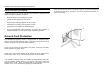
Controller Overview Controller Location Floppy Disk Drive Location Control Panel Controller Controller On/Off Switch Switches the N5T controller on and off. Not present for N5T with Tag 3, EV4, or CNG. Circuit Breaker & GFI Removes power to printer and controller if electrical fault is detected. Turns N5T (with Tag 3), EV4 and CNG Controllers on and off. Press the RED button to power off; BLACK to power ON. Printer On/Off Switch Switches the printer on and off.
8825/8830 Controller Setup Manual for Firmware 6.
Controller Port Location (continued) New EV4 Controller for use with the 8825 Printer N5T/CNG Product Code (Note: This inverted orientation of ports denotes an N5T Tag 3 Controller.) 10/100 Ethernet Serial Ethernet (RJ-45) Multiprotocol Network Interface Card (Legacy card on N5T, CNG uses optional adapter on Parallel Port.) Parallel Ethernet (BNC) VPI Extra slot for adding an optional PCI Mezzanine Card, or for installation of 7346/56 SCSI Kit.
8825/8830 Controller Setup Manual for Firmware 6.0 6 Controller Overview (continued) Printer Control Panel The purpose of this page is to familiarize you with the location of the 8825/8830 printer Control Panel LEDs and buttons. Details on the LEDs and buttons are available in the sections of this chapter entitled Graphic & Message Displays and Control Panel buttons respectively.
Controller Overview (continued) Learning the Displays On-Line Indicator Light There is one LED (Light Emitting Diode) on the 8825/8830 Printer’s Control Panel. The LED which is located below the Display Window is: LED NAME ON-LINE FUNCTION ON-LINE LED is lit when the printer is set to accept print jobs through local ports or across the network. The ON-LINE LED is off when the printer has been deselected and will not print jobs*.
8825/8830 Controller Setup Manual for Firmware 6.0 Controller Overview (continued) Learning the Control Panel Buttons ON-LINE If the printer is On-line (operating), pressing this key will pause the printer. Jobs will still be accepted from the various host interfaces and spooled to DRAM or hard disk; however, print data will not be sent to the print engine. When the printer is not paused, the associated LED next to this button will be lit.
Controller Overview (continued) Learning the Control Panel Buttons (continued) PREVIOUS In a menu mode, this key moves the current menu selection to the previous item in whatever menu is currently being displayed. It operates in a “wrap-around” fashion. Numeric Keypad and CANCEL/CLEAR button In the setup defaults mode, the digits 0 through 9, and the decimal key, are used to input numeric information.
8825/8830 Controller Setup Manual for Firmware 6.0 Controller Overview (continued) Over The Wire Software License Feature Enabling Beginning with the release of Firmware 4.0, optional software features can be enabled by using the Document Submission Tool (part of AccXES Client Tools) or the Web Printer Manager Tool* to send a “feature key” file to the Controller over the network, serial, or parallel cable connection. Typical Method for Enabling Software License Features 1.
Controller Overview (continued) Software License Feature Enabling (continued) Effect of Purchased Hardware on the Need to Enable Software License Features The need to enable Software License Features depends upon purchased equipment as stated below: Scan-to-Net Licensed Feature If this feature is desired, a Scan-to-Net license is required for all systems using a 7346 scanner (such as the 8825 DDS).
8825/8830 Controller Setup Manual for Firmware 6.0 Controller Overview (continued) Over The Wire Firmware Upgrading Coinciding with the release of Firmware 4.0 and the availability of the new Web Printer Manager Tool, it is now possible to upgrade Firmware versions with new releases by sending a file to the Controller over the network, serial, or parallel cable connection. Customers can obtain new Firmware releases from the internet or in the form of a CD ROM upgrade.
Controller Overview (continued) Controller Specifications(EV4 Controller for 8825) Physical Characteristics The Controller is attached to the side panel of the 8825 Printer as an embedded device. Electrical Requirements 100 - 250 VAC auto-ranging power supply. Agency Approvals Safety: UL 1950, CA22.2 No. 950 (CUL), EN 60950 (CE Mark) EMC: CE Mark, FCC Class A, Canada Radio Interference Regulations Class A, VCCI Class 1 Hardware Specifications CPU Power PC 8240 (603e) operating at 250 MHz clock speed.
8825/8830 Controller Setup Manual for Firmware 6.0 Controller Overview Controller Specifications (EV4 for 8825) (continued) I/O Ports Serial Two 9 pin Host serial ports provided. One is used by the 8825 DDS scanner (7346 or 7356) when this option is connected. The second is used as an input port for receiving data via serial port connection. Parallel (IEEE 1284 Compliant) High density port connector provided. SCSI Optional 50 pin SCSI-2 card available. VPI Optional card available.
Note: The hard drive is required for installation of 6.0 firmware. Controller Overview Controller Specifications (N5T/CNG Product Code) Physical Characteristics The Controller is attached to the side panel of the 8830 Printer as an embedded device. Electrical Requirements 100 - 250 VAC auto-ranging power supply. Agency Approvals Safety: UL 1950, CA22.2 No.
8825/8830 Controller Setup Manual for Firmware 6.0 Controller Overview Controller Specifications (N5T/CNG Product Code) (continued) I/O Ports Serial Two 9 pin Host serial ports provided. One is used by the 8825/8830 DDS scanner when this option is connected. The second is used as an input port for receiving data via serial port connection. Note: For firmware releases 2.0, the upper serial port is used for data input; the lower serial port is used for service.
Controller Overview (continued) Job Printing/Processing Specifications Network Protocols Legacy 3003-XTP NIC (replaced by External Ethernet Adapter) TCP/IP (lpr/lpd, telnet, TFTP puts,...) EtherTalk Novell IPX/SPX PServer for Ver. 3.x and 4.x w/NDS NetBEUI DLC/LLC • • • PostScript PPD System Print Driver AccXES Client Tools Web PMT (requires Firmware Release 4.0 or higher) Windows NT 4.
8825/8830 Controller Setup Manual for Firmware 6.0 18 Job Queue Management Controller Overview Job Printing/Processing Specifications (continued) Single prioritized queue, adjustable priority, job canceling, queue monitoring provided. UNIX platform: Long plot • • • • • Up to 80 feet (24.38 Meters) printing. tftp puts and ftp telnet lpr/lpd support AccXES Client Tools (Solaris) Web PMT (requires Firmware Release 4.0 or higher) Job Control Language HP-PJL with custom extensions.
Electronic Collation Controller Overview Job Printing/Processing Specifications (continued) Extended Processing Options • Autoscaling • Autorotation • Auto Size Detect • Banner Sheets • Rotation (0, 90, 180, 270) • Scaling (10% to 999%) • Justification • Margins • Raster Stamps • Labeling • Page Composition/Plot Overlay • Mirror • Vector Halftone • Media Mismatch Management • Plot Nesting • Control Panel Lockout • Scan-to-Net (8825 DDS optional) • Job Accounting (8825 &
8825/8830 Controller Setup Manual for Firmware 6.0 Controller Overview (continued) Preparing The Serial Ports 20 • • • HDI Driver for AutoCAD 2000 and 2000i PostScript PPD System Print Driver Document Submission Tool (part of AccXES Client Tools) UNIX PLATFORM: The Host Serial Port This port requires a null modem serial cable to be connected from the Controller host serial port to the workstation serial port.
Controller Overview (continued) Preparing The Serial Ports (continued) Data Formats Supported • HP-GL, HP-GL/2 • HP-RTL • TIFF, NIRS • CALS 1 & 2 • CalComp 906/907/951/PCI with Electrostatic extensions • VDS (Versatec Data Standards) • VCGL • CGM • C4 • Filenet • Versatec Raw Raster • Optional PostScript 3 with PDF 8825/8830 Controller Setup Manual for Firmware 6.
8825/8830 Controller Setup Manual for Firmware 6.0 Controller Overview (continued) 22 Null Modem Cable Pin Out Preparing The Serial Ports (continued) Serial Cable Description The serial cable should be wired as a null modem with a standard 9 pin D connector at the controller end and a connector to match the workstation serial port connector at the host end.
Controller Overview (continued) Preparing The Parallel Port Parallel Port This port requires connecting a parallel cable between your workstation's parallel port and the Controller parallel port. An appropriate software print driver or system command is necessary to direct jobs to the printer. Enabling the parallel port is done from the Web Printer Manager Tool or from the 8825/8830 Control Panel.
8825/8830 Controller Setup Manual for Firmware 6.
Controller Overview (continued) VPI Connector Pin Out Preparing The VPI Port Connector Pin Number Signal Name Connector Pin Number Signal Name 1 IN01+ 20 IN01- 2 IN02+ 21 IN02- 3 IN03+ 22 IN03- 4 IN04+ 23 IN04- 5 IN05+ 24 IN05- Use the Setup I/O Ports menu of the Printer Control Panel to enable the VPI port.
8825/8830 Controller Setup Manual for Firmware 6.
Dynamic Host Configuration via: Controller Overview (continued) Preparing The 3003-XTP NIC Ethernet Port Ethernet Port (Legacy NIC for N5T Controller) The optional, 3003-XTP Network Interface Card (NIC) provides connectivity to two standard Ethernet type networks. 10Base2 (BNC Thinnet) and 10BaseT (Twisted Pair RJ-45) connectors are both available and the NIC auto-senses the active connector.
8825/8830 Controller Setup Manual for Firmware 6.0 Controller Overview 28 WINDOWS NT 4.
Controller Overview RJ-45 Connector Pin Assignments Preparing The 3003-XTP NIC Ethernet Port (continued) Data Formats Supported • HP-GL, HP-GL2 • HP-RTL • CalComp 906 /907 /951 /PCI • TIFF 6.
8825/8830 Controller Setup Manual for Firmware 6.0 30 • Controller Overview (continued) Preparing The 10/100 Ethernet Port Overview This port is standard on the all Controllers. To print using this port your workstation must have a Network Interface Card installed, protocols enabled, and appropriate software running. Enable Controller Ethernet Port Use the Setup I/O Ports menu of the Printer Control Panel to set the Ethernet “Port Enable” to “ADVANCED.
Controller Overview Preparing The 10/100 Ethernet Port (continued) RJ-45 Connector Pin Assignments Data Formats Supported • HP-GL, HP-GL2 • HP-RTL • CalComp 906 /907 /951 /PCI • TIFF 6.
8825/8830 Controller Setup Manual for Firmware 6.0 Controller Overview (continued) Menu Tree Access Instructions and Overview Access Instructions The Controller has three operating conditions as indicated in the display window of the Printer Control Panel. These conditions are: PAUSED, IDLE, and PROCESSING. All the printer setup menus must be accessed in the PAUSED mode.
Menu Tree Overview UTILITIES SETUP I/O PORTS SETUP PRINTER PROCESSING DEFAULTS SYSTEM ADMINISTRATION PRINTER MENU TEST PRINT SCSI BANNER PAGE ELECTRONIC COLLATION JOB ACCOUNTING AUDIBLE INDICATORS* SYSTEM INFORMATION ETHERTALK (for legacy 3003-XTP NIC) DIAGNOSTICS PAGE NUMBER OF COPIES CHANGE PASSWORD TIMERS** POSTSCRIPT PARTITION NETBEUI (for legacy 3003-XTP NIC) TONER DENSITY EMULATION MENU LOCKOUT PRINTER ADJUSTMENTS* JOB QUEUE IPX/SPX (for legacy 3003-XTP NIC) ERROR PAGE JOB P
8825/8830 Controller Setup Manual for Firmware 6.0 Accessing the Default Setup Menus 34 POSTSCRIPT PARTITION NORMAL OPTIMIZED NONE JOB QUEUE Quick Menu Locator The Controller status is one of three conditions as indicated by the display panel. The conditions are: PAUSED, IDLE, and PROCESSING. All the controller default setup menus must be accessed in the PAUSED mode.
Accessing the Default Setup Menus (continued) Quick Menu Item Locator SETUP I/O PORTS MENU SCSI PORT ENABLE TARGET ID BUS TERMINATION ENABLE ETHERTALK (for legacy 3003-XTP NIC) PORT ENABLE PHASE NETBEUI (for legacy 3003-XTP NIC) PORT ENABLE SERIAL PORT ENABLE BAUD RATE 300 - 19,200 FLOW CONTROL NONE, XON/XOFF, RTS/CTS, BOTH (XON/XOFF & RTS/CTS).
8825/8830 Controller Setup Manual for Firmware 6.
Accessing the Default Setup Menus RESOLUTION ( 50 - 4064 dpi ) Quick Menu Item Locator EOP DETECTION SETUP PRINTER MENU (continued) SEARCH ADDRESS ( 999, 9999, BOTH, or NONE ) EOP COMMAND ( 1, 2, or NONE ) PAUSE COMMAND EMULATIONS HPGL NEW PLOT COMMAND MANUAL COMMAND MODE ( HPGL2 or HPGL758X ) EOP DETECTION PG COMMAND RP COMMAND PLOTTER OFF COMMAND TOP OF FORM COMMAND START PLOT COMMAND FORCE PLOT COMMAND CALCOMP PALETTE ( INPUT NUMBER OF PALETTE ) CALCOMP PALETTE SOURCE ( JOB or PRINTER ) FR COMM
8825/8830 Controller Setup Manual for Firmware 6.
Accessing the Default Setup Menus Quick Menu Item Locator SETUP PRINTER MENU (continued) VELLUM MISMATCH MODE SCALING QUERY SUBSTITUTE MISMATCH QUEUEING ENABLE (ON or OFF) PEN PALETTE INPUT NUMBER ( 0 - 8 ) COLOR NUMBER ( 0 - 150 ) PEN PATTERN ( 0 - 49 ) ACTIVE PARAMETER SET INPUT NUMBER ( 0 - 9 ) PLOT NESTING MODE ENABLE (ON or OFF) EXCLUSIVE ENABLE (ON or OFF) TIMEOUT MARGIN MAXIMUM LENGTH 8825/8830 Controller Setup Manual for Firmware 6.
8825/8830 Controller Setup Manual for Firmware 6.0 Accessing the Default Setup Menus Quick Menu Item Locator PROCESSING DEFAULTS MENU ELECTRONIC COLLATION ( ON or OFF ) NUMBER OF COPIES ( 1 - 999 ) EMULATION AUTO, CALCOMP, CALS1, CALS2, CGM, HPGL, TIFF6, VDS, C4, FILENET, POSTSCRIPT, VRASTER JOB PRIORITY INPUT VALUE ( 1 - 10 ) FINISHER OPTIONS NO FOLD, 190MM, 190+20MM, 210MM, 8.5X11, 7.5X11, 7.
Accessing the Default Setup Menus ROLL 2 Quick Menu Item Locator ROLL 3 PROCESSING DEFAULTS MENU (continued) MANUAL FEED MEDIA TYPE MARGIN BOTTOM INPUT MM ( 0 - 2540 mm) BOND FILM VELLUM MARGIN LEFT ANY INPUT MM ( 0 - 2540 mm) MIRROR IMAGE MARGIN RIGHT INPUT MM ( 0 - 2540 mm) OFF MIRROR X MIRROR Y OVER SIZE MARGIN MIRROR XY INPUT % ( 0 - 100 % ) UNDER SIZE MARGIN INPUT % ( 0 - 100 % ) PAPER SIZE DETECT PLOT SPECIFIED DRAWN AREA MEDIA SOURCE AUTO ROLL 1 8825/8830 Controller Setup Manual for Fir
8825/8830 Controller Setup Manual for Firmware 6.
LABEL STRING NONE NAME TIME DATE LOCATION X TRAILING EXTEND NUMERIC LEFT CENTER RIGHT LEADING LOCATION Y BOTTOM NUMERIC TOP CENTER LABEL SIZE INPUT POINT ( 6- 72 ) ROTATE INPUT % ( 0 - 359 ) LABEL SHADING INPUT % (0 – 100) FONT Select FONT from INSTALLED FONT NAMES 8825/8830 Controller Setup Manual for Firmware 6.
8825/8830 Controller Setup Manual for Firmware 6.0 44 Accessing the Default Setup Menus Quick Menu Item Locator PRINTER MENU SYSTEM ADMINISTRATION MENU Refer to the 8825/8830 Printer Operator Manual to set these printer functions.
Viewing The System Configuration Defaults EXITING TEST PRINT UTILITY Press the ON-LINE key to go back to ON-LINE mode and print the TEST PRINT(s). Making a Test Print TEST PRINT PURPOSE The purpose of Test Prints is to provide a record of current system settings for use in daily operations, Network Communications setup, and restoration of desired parameters in cases of unexpected change (such as through accidental use of the Restore Factory Default utility).
8825/8830 Controller Setup Manual for Firmware 6.0 Displaying Job Accounting Reports Purpose As implemented in Firmware Release 4.0, the Controller provides the ability to track media usage from all print jobs containing account number data. This data is provided by the user of such workstation tools as print drivers and the Document Submission Tool.
Changing the PostScript Partition Parameter Purpose CAUTION Changing the partition option will cause the loss of any scanned documents stored on the hard disk drive during previous scan-to-net operations. Retrieve these documents before re-partitioning the hard disk drive. • Pressing [ENTER] implements the selected change of partition. The Controller will automatically reboot to re-partition the hard drive. The display indicates, REBOOTING PLEASE WAIT...
8825/8830 Controller Setup Manual for Firmware 6.0 Displaying The Mismatch Queue Purpose The purpose of this feature is to provide access to the “Mismatch Queue” which provides for continuous printing when a requested media type or size is not installed and scaling to fit existing sizes of installed media, or printing on any type of installed media, are not acceptable options.
Configuring the System Communication Defaults Path to SCSI options Display , press [ON-LINE], display , press [ENTER], display , press [NEXT], display , press [ENTER], display Selecting SCSI options Note: For more detailed information about connecting the Printer to a network environment, refer to the Network Administrator’s Guide. Setting The SCSI Options Press ENTER to change any options. The first option is SCSI port enable (ON or OFF).
8825/8830 Controller Setup Manual for Firmware 6.0 Configuring the System Communication Defaults (continued) 50 NOTE: These zone and printer name settings are set using the Xerox 8825/8830 Printer Manager Tool software. These optional settings may be required by your network environment. Consult your network administrator for the requirements for your specific configuration.
Configuring the System Communication Defaults (continued) Path to the NETBEUI option Display , press [ON-LINE], display , press [ENTER], display , press [NEXT], display , press [ENTER], display , press [NEXT] until is displayed.
8825/8830 Controller Setup Manual for Firmware 6.0 Configuring the System Communication Defaults (continued) Setting The IPX/SPX options (Legacy 3003-XTP NIC) The IPX/SPX Purpose The purpose of this option is to set the multiprotocol 3003-XTP NIC to be enabled to use the IPX/SPX protocol. The 10/100 Ethernet card/port does not support the IPX/SPX protocol. All Controllers now use an optional, external Ethernet Adapter to support IPX/SPX.
Configuring the System Communication Defaults (continued) SETTING THE TCP/IP MASK ADDRESS OF THE PRINTER ON THE NETWORK Range: String of the form nnn.nnn.nnn.nnn. Default: “255.255.252.0” Setting The TCP/IP Options The TCP/IP Purpose The purpose of these options is to set any of the Controller Ethernet network interfaces to be used with the TCP/IP protocol. Note: This value means “there is no gateway used on this network.” Never set this value to 0.0.0.0; doing so can disrupt operations on your network.
8825/8830 Controller Setup Manual for Firmware 6.0 Setting the TCP/IP Options (continued) Path to the TCP/IP options Display , press [ON-LINE], display , press [ENTER], display , press [NEXT], display , press [ENTER], display , press [NEXT] until is displayed. SELECTING THE TCP/IP OPTIONS Press ENTER to display PORT ENABLE. Press the ENTER key to change the option.
Configuring the System Communication Defaults (continued) Note: For firmware releases 1.0 −2.0, the upper serial port was used for data input; the lower serial port was used for service. The Serial Purpose For newer firmware releases (2.5, 2.7, 3.0), the upper serial port is used for connection to the 8825/8830 DDS Control Panel if a scanner is detected during startup. If a scanner is not detected during startup, the upper serial port becomes the service port.
8825/8830 Controller Setup Manual for Firmware 6.0 Configuring the System Communication Defaults (continued) Setting The Serial Options (continued) SELECTING THE SERIAL OPTIONS Press the ENTER key to display PORT ENABLE. Press the ENTER key, then the NEXT key to select either ON or OFF. When the desired mode is displayed press the ENTER key. Press the NEXT key followed by ENTER to change the Baud Rate.
Configuring the System Communication Defaults (continued) Setting The Parallel Option The Purpose of the Parallel Option The purpose of this option is to enable the Controller parallel port. Software drivers may be required to be loaded at the customer workstation to enable printing and control of the 8825/8830 Printer. SETTING THE CONTROLLER PARALLEL PORT EITHER ON OR OFF.
8825/8830 Controller Setup Manual for Firmware 6.0 Configuring the System Communication Defaults (continued) Setting The VPI Options VPI Purpose The purpose of these options is to enable the Controller VPI port, if available. Software drivers may be required to be loaded at the customer workstation to enable printing and control of the 8825/8830 Printer. ENABLING OR DISABLING THE CONTROLLER VPI PORT. Range: ON or OFF Default: ON ENABLING THE CONTROLLER VPI PORT TIME OUT FUNCTION.
Configuring the Printer Setup Defaults Setting The Banner Page Options Banner Page Purpose Selecting Banner Page options Press the ENTER key to display . Press ENTER again to change the option. Press the NEXT key to select either ON or OFF. When the desired mode is displayed press the ENTER key. Press the NEXT key to display position. Press the ENTER key to change the position option. Press the NEXT key to select Before Job or After Job. When the desired mode is displayed press the ENTER key.
8825/8830 Controller Setup Manual for Firmware 6.0 60 Configuring the Printer Setup Defaults (continued) SELECTING DIAGNOSTICS PAGE OPTION Setting The Diagnostics Page Option Press the ENTER key to display ENABLE. Press ENTER to change the option. Press the NEXT key to select either ON or OFF. When the desired mode is displayed press the ENTER key.
Typical Diagnostics Page 8825/8830 Controller Setup Manual for Firmware 6.
8825/8830 Controller Setup Manual for Firmware 6.0 62 SELECTING IMAGE DENSITY OPTION Configuring the Printer Setup Defaults (continued) Setting The Image Density (Toner) Option Image Density Purpose The purpose of this option is to set the toner density on the printed page. The number (0) sets a minimum image density level, and the number (10) sets a maximum image density level.
Configuring the Printer Setup Defaults (continued) Setting The Error Page Option Error Page Purpose The purpose of this option is to enable the printing of Error Pages. Error pages may prove useful when troubleshooting print job errors. The two levels of error reporting are designated as level 1 and level 2. A brief description of each level follows: The LEVEL 1 selection prints an ERROR/WARNING page only when a hard error exists that will not allow the data file to print.
8825/8830 Controller Setup Manual for Firmware 6.
SELECTING IMAGE SCALE OPTION Configuring the Printer Setup Defaults (continued) Setting The Image Scale Option Press the ENTER key to change the option. Press the NEXT key to select PHOTO or LINE, then press the ENTER key with the desired selection displayed. EXITING IMAGE SCALE OPTION Image Scale Purpose The purpose of this option is to define the default scale function as either line or photo mode. Press EXIT to set up additional functions. Press the ON-LINE key to go back to ON-LINE mode.
8825/8830 Controller Setup Manual for Firmware 6.0 66 Configuring the Printer Setup Defaults (continued) Setting the Vector Halftone Option Note: This feature is not supported when using PostScript. SELECTING THE VECTOR HALFTONE OPTION Press the ENTER key to change the option. Press the NEXT key to select AREA OPTIMIZED or LINE OPTIMIZED, then press the ENTER key with the desired selection displayed. If problems occur with fine lines being omitted, mainly in filled areas, try selecting LINE OPTIMIZED.
Configuring the Printer Setup Defaults (continued) Setting The Date and Time Option The Purpose of the Date and Time Option This utility sets the date and time that is used to time stamp the banner pages, error pages, and plot labels. Note: The date/time function is year 2000-compliant until the year 2038. PATH TO THE DATE AND TIME OPTION SELECTING THE DATE AND TIME OPTION Press the ENTER key to display MONTH. Press ENTER to enable changes. Press ENTER again to confirm changes.
8825/8830 Controller Setup Manual for Firmware 6.0 Configuring the Printer Setup Defaults (continued) Setting The Time Out Option The Purpose of the Time Out Setting The Time Out adjustment (range 5 to 300 seconds) sets the time out duration of the Serial and Parallel communication ports. The default setting is 5 seconds.
Configuring the Printer Setup Defaults (continued) Setting The Maximum Plot Length Option The Purpose of the Maximum Plot Length Option This option sets the maximum plot length which can be printed, in inches. Range: 48 inches (4 feet) (122 cm) to 960 inches (80 feet) (2438 cm) Default: = 960 inches (2438 cm) The value displayed on the Control Panel is expressed in centimeters. There are 2.54 cm in one inch.
8825/8830 Controller Setup Manual for Firmware 6.0 70 Configuring the Printer Setup Defaults (continued) to PRINTER so that the palette named by HPGLPALETTE determines the pen settings. Setting The HPGL Emulation Options Range: JOB, or PRINTER HPGL Emulation Purpose SETTING THE MERGE CONTROL OPTION Default: JOB Default: HPGL2 The Merge Control Default Feature determines how the pixels of intersecting lines or graphics will be shown in your printed job.
Configuring the Printer Setup Defaults (continued) PATH TO HPGL EMULATION OPTIONS Display , press [ON-LINE], display , press [ENTER], display , press [NEXT] until is displayed, press [ENTER], display , press [NEXT] until is displayed, press [ENTER], display SELECTING THE HPGL EMULATION OPTIONS Press the ENTER key to display MODE and press ENTER.
25/8830 Controller Setup Manual for Firmware 6.0 Configuring the Printer Setup Defaults (continued) Setting The CalComp Emulation Options CalComp Emulation Purpose The purpose of these options is to set the defaults of the Controller when using the CalComp emulation mode. ENABLING THE CALCOMP CHECK SUM OPERATION. Range: ON or OFF Default: ON 72 Default: 2032 SETTING THE CONTROLLER TO TERMINATE THE CALCOMP FILE WHEN EITHER 1 OR 2 EOP COMMANDS ARE RECEIVED.
Configuring the Printer Setup Defaults Setting The CalComp Emulation Options (continued) PATH TO CALCOMP EMULATION OPTIONS Display , press [ON-LINE], display , press [ENTER], display , press [NEXT] until is displayed, press [ENTER], display , press [NEXT] until is displayed, press [ENTER], display , press [NEXT], display SELECTING THE CALCOMP EMULATION OPTIONS Press the ENTER key to change CalComp checksum option.
8825/8830 Controller Setup Manual for Firmware 6.0 Configuring the Printer Setup Defaults 74 Setting The CalComp Emulation Options (continued) The user-defined palettes can also be specified using the Xerox Printer Manager Tool software. The pen width, pattern, and color can all be controlled individually for each pen. EXITING CALCOMP EMULATION OPTIONS You may set whether the job or the palette controls the attributes per pen and per attribute. Press EXIT to set up additional functions.
Configuring the Printer Setup Defaults (continued) Default: FILE CONTROL Setting The CGM Emulation Options PATH TO CGM EMULATION OPTIONS CGM Purpose SETTING THE DEFAULT PAPER SIZE FOR CGM PLOTS This option sets the default paper size for CGM plots that do not have a size assigned or where both dimensions are greater than 36 inches. The value is similar to Paper Size but must have 2 dimensions; therefore, ANY or a ROLL size cannot be used.
8825/8830 Controller Setup Manual for Firmware 6.
Configuring the Printer Setup Defaults (continued) SELECTING THE VDS EMULATION OPTIONS Setting The VDS Emulation Options Press the ENTER key to enter the VDS menu. Press the NEXT key to toggle to CHARACTER SET. Press ENTER, then the NEXT key to toggle the choices, EBCDIC or ASCII. When the desired choice is displayed press the ENTER key. VDS Emulation Purpose Press the NEXT key to toggle to VDS PALETTE. Press ENTER and input the desired PALETTE number, then press the ENTER key.
8825/8830 Controller Setup Manual for Firmware 6.0 Configuring the Printer Setup Defaults (continued) Setting The TIFF Emulation Options TIFF Emulation Purpose This option sets the way the Controller processes TIFF job files. The way the option is set causes the Controller to ignore or use the tag contained in a TIFF job which sets the minimum code value to black in single bit TIFF data.
Configuring the Printer Setup Defaults (continued) Setting The Versatec Color Graphics Language (VCGL) Emulation Printer Control Panel’s menu and submenu, or using the Printer Management Tool (PMT) installed on a remote workstation. Depending upon whether the Palette Source Parameter is set to or to , the pen settings specified within your CAD application, or the pen palette specified by a palette number, will be used to print your drawing.
8825/8830 Controller Setup Manual for Firmware 6.0 Setting The VCGL Emulation (continued) Color = Since the 8825/8830 printer is a black and white printer only, the representation of color is by matching shades of gray to the 0 to 255 colors of the VCGL file, or by representing colors with a black pattern if the color is defined in the drawing file as a particular pattern in black.
Configuring the Printer Setup Defaults (continued) Setting The PostScript Default Media Size Option This parameter is used for those PostScript files that do not specify an output size. Valid values are specific sheet sizes supported by the Controller. ROLL sizes and the ANY selection cannot be used. The available range is: ANSI A, ANSI B, ANSI C, ANSI D, ANSI E, ARCH A, ARCH B, ARCH C, ARCH D, ARCH E, ARCH 30, ISO A0, ISO A1, ISO A2, ISO A3, ISO A4, ISO B1, ISO B2, ISO B3, or ISO B4.
8825/8830 Controller Setup Manual for Firmware 6.0 82 Configuring the Printer Setup Defaults (continued) SELECTING THE BOND MISMATCH OPTIONS Setting The Bond Mismatch Option Press the ENTER key to change option. Press the NEXT key until the desired mode QUERY or SCALING is displayed, then press the ENTER key. Bond Mismatch Purpose This option sets the media size mismatch recovery mode. When set to SCALING, the printer will scale the print to the nearest paper roll to your requested print size.
Configuring the Printer Setup Defaults (continued) Setting The Film Mismatch Option Film Mismatch Purpose This option sets the media size mismatch recovery mode. When set to SCALING, the printer will scale the print to the nearest film roll to your requested print size. When obtaining the correct sheet size is important, you should specify QUERY. When set to QUERY, the printer pauses until the correct media is installed.
8825/8830 Controller Setup Manual for Firmware 6.0 Configuring the Printer Setup Defaults (continued) Setting The Vellum Mismatch Option Vellum Mismatch Purpose This option sets the media size mismatch recovery mode. When set to SCALING, the printer will scale the print to the nearest vellum roll to your requested print size. When obtaining the correct sheet size is important, you should specify QUERY. When set to QUERY, the printer pauses until the correct media is installed.
Configuring the Printer Setup Defaults (continued) Setting The Mismatch Queueing Enable (On or Off) Purpose To prevent print jobs or individual pages, which do not match any Bond, Film, or Vellum media installed in the printer, from halting the printing process, set the Mismatch Queueing Enable to ON. You must also set the Bond, Film, or Vellum Mismatch Option, as separately described in this manual, to QUERY.
8825/8830 Controller Setup Manual for Firmware 6.0 Configuring the Printer Setup Defaults (continued) Setting The Pen Palette Options Pen Palette Purpose There are eight user definable palettes (1 - 8), and one factory default palette which cannot be changed (palette 0). Palettes may be assigned for use by any of four data format interpreters (HPGL/2, CGM, CalComp, VDS/VRF and VDS/ordered vector format).
Configuring the Printer Setup Defaults (continued) Setting The Active Parameters Option Active Parameters Purpose This option lets you set up nine sets of custom job parameters with a number of 1 to 9 assigned to each set of parameters. A single digit can then assign a complete custom set to a job file. The 0 set is the normal printer default set of options.
8825/8830 Controller Setup Manual for Firmware 6.0 Configuring the Printer Setup Defaults (continued) Setting The Plot Nesting Option PURPOSE The purpose of Plot Nesting is to efficiently group the printing of plots on a single sheet of media to eliminate media waste. Plot Nesting enables one or more plots from one or more user jobs to be arranged on the widest roll of printer-installed media in an efficient, non-overlapping manner.
Configuring the Printer Setup Defaults • Labels – Positioning will be relative to the logical page. Setting The Plot Nesting Option (continued) • Mirror – Applies to the logical page. • Page Scaling (auto and numeric) – applies to the logical page; may cause the page to become “non-nestable,” if the short edge of the scaled logical page is greater than 18 inches.
8825/8830 Controller Setup Manual for Firmware 6.0 Configuring the Printer Setup Defaults Setting The Plot Nesting Option (continued) EVENTS BREAKING THE NEST • A plot is received and Nesting Mode is disabled. • A plot is received and Nesting Exclusive is enabled. • A plot is received with a page width over 18”. • Nesting Time Out has elapsed. • A plot requiring a change of media type is received. • A Page Composition job is received. • Finisher options other than FOLD_BYPASS are specified.
Configuring the Printer Processing Defaults Setting the Electronic Collation option SELECTING THE ELECTRONIC COLLATION OPTION Press the ENTER key to change option. Press the NEXT key to toggle through the selections ON or OFF, and when the desired selection is displayed, press the ENTER key. EXITING ELECTRONIC COLLATION OPTION Press EXIT to set up additional functions. Press the ON-LINE key to go back to ON-LINE mode.
8825/8830 Controller Setup Manual for Firmware 6.0 Configuring the Printer Processing Defaults (continued) Setting the Number of Copies option Number of Copies Purpose The purpose of this option is to specify the quantity of copies printed of each page.
Configuring the Printer Processing Defaults (continued) Setting the Emulation options Emulation Purpose The purpose of this option is to assign the Controller emulation default to either Automatic Format Detection (AFR) or to a specific emulation. An example of using this option is if your site normally prints only TIFF files, by specifying the default to be TIFF the execution speed will be slightly increased. In this case the HP-PJL ENTER LANGUAGE command of a job file is used as a ‘hint’ by the AFR.
8825/8830 Controller Setup Manual for Firmware 6.0 94 Configuring the Printer Processing Defaults (continued) Setting The Job Priority Option Job Priority Purpose The purpose of this option is to set a value to code the job scheduling priority. Range: 1 - 10 Default: 5 Changing the job priority value at the Printer Control Panel causes a change in the priority of all jobs. The scale of the job value is: 1 is the highest priority and 10 is the lowest.
Setting The Job Priority Option (continued) How Job Priority Scheduling Works in the Controller (continued) • The job with the highest priority number in the queue of eligible jobs is scheduled first. If more than one job has the same priority number, the job received in total and first in time will be printed first.
8825/8830 Controller Setup Manual for Firmware 6.0 Configuring the Printer Processing Defaults (continued) Setting the Finisher options Finisher Option Purpose The purpose of this option is to select the default folding style. Available selections depend on the folder model installed. This option is to be selected when the On-line Folder is installed. Range: FOLD BYPASS, FOLD 190, FOLD 210, FOLD 190 MARGIN, FOLD ANSI A, FOLD ARCH A, FOLD 7.5X11, or FOLD 7.
Configuring the Printer Processing Defaults (continued) Setting the Finishing Long Plot Option Purpose For the finishing of long plots of up to 48 feet with 64MB of RAM and 80 feet with 96MB of RAM, when equipped with an optional On-line Folder you can specify long plot finishing of NO FOLD or Z FOLD.
8825/8830 Controller Setup Manual for Firmware 6.0 98 Configuring the Printer Processing Defaults (continued) PATH TO THE JUSTIFICATION X OPTION Setting the Justification X Set Option Display , press [ON-LINE], display , press [ENTER], display , press [NEXT] until is displayed, press [ENTER], display , press [NEXT] until is displayed.
Configuring the Printer Processing Defaults (continued) PATH TO THE JUSTIFICATION Y OPTION Setting the Justification Y Set Option Display , press [ON-LINE], display , press [ENTER], display , press [NEXT] until is displayed, press [ENTER], display , press [NEXT] until is displayed.
8825/8830 Controller Setup Manual for Firmware 6.0 Configuring the Printer Processing Defaults (continued) Setting the Top Margin option Top Margin Purpose The purpose of this option is to set the default value for the top margin of the print in millimeters.
Configuring the Printer Processing Defaults (continued) Setting the Bottom Margin option Bottom Margin Purpose The purpose of this option is to set the default value for the bottom margin of the print in millimeters.
8825/8830 Controller Setup Manual for Firmware 6.0 Configuring the Printer Processing Defaults (continued) Setting the Left Margin option Left Margin Purpose The purpose of this option is to set the default value for the left margin of the print in millimeters.
Configuring the Printer Processing Defaults (continued) Setting the Right Margin option Right Margin Purpose The purpose of this option is to set the default value for the right margin of the print in millimeters. Range: 0 – 2540 mm Default: 5 mm PATH TO RIGHT MARGIN OPTION Display , press [ON-LINE], display , press [ENTER], display , press [NEXT] until is displayed, press [ENTER], display , press [NEXT] until is displayed.
8825/8830 Controller Setup Manual for Firmware 6.0 Configuring the Printer Processing Defaults (continued) Setting the Oversize Margin option Oversize Margin Purpose When PAPER is set to a value for auto size detection (ANY, ANY ANSI, ANY ARCH, or ANY ISO), then this parameter determines the threshold for selecting a larger, installed paper size to fit the printed image within the margin tolerances selected.
Configuring the Printer Processing Defaults (continued) Setting the Undersize Margin option Undersize Margin Purpose When PAPER is set to a value for auto size detection (ANY, ANY_ANSI, ANY_ARCH, or ANY_ISO), then the undersize margin option determines the threshold for selecting a smaller, installed paper size to fit the printed image within the tolerances selected.
8825/8830 Controller Setup Manual for Firmware 6.0 106 Configuring the Printer Processing Defaults (continued) Setting the Paper Size Detect Set (use marked area) Option Paper Size Detect Purpose Note: This parameter only affects HPGL and HPGL/2 jobs.
Configuring the Printer Processing Defaults (continued) Setting the Media Source Option EXITING THE MEDIA SOURCE OPTION Press EXIT to set up additional functions. Press the ON-LINE key to go back to ON-LINE mode. Media Source Option Purpose This option sets the default roll position to be used for all jobs.
8825/8830 Controller Setup Manual for Firmware 6.0 Configuring the Printer Processing Defaults (continued) Setting the Media Type Set Option Media Type Option Purpose This option sets the default type of media that will be used for all jobs. Range: BOND, VELLUM, FILM, or ANY Default: BOND Note: If a job is sent to the printer and the desired media type is not installed, the user will be prompted to load the correct media type.
Configuring the Printer Processing Defaults (continued) Setting the Set Mirror Image Option EXITING THE SET MIRROR IMAGE OPTION Press EXIT to set up additional functions. Press the ON-LINE key to go back to ON-LINE mode. Purpose of Set Mirror Image Option The purpose of this option is set the desired Controller default mirror image mode. This option sets the default Mirrors mode that will be used when every image is printed.
8825/8830 Controller Setup Manual for Firmware 6.0 Configuring the Printer Processing Defaults (continued) Setting the Page Rotate Set Option Purpose of Set Page Rotate Option This option sets the printer for auto-rotating each page for best fit to the available media, or to a specified preset of rotation. Range: 0, 90, 180, 270, or AUTO Default: AUTO This is applied in the following priority order: • Instructions embedded within a print job’s native data format are applied with highest priority.
Configuring the Printer Processing Defaults (continued) Setting the Set Page Scaling Option EXITING THE SET PAGE SCALING OPTION Press EXIT to set up additional functions. Press the ON-LINE key to go back to ON-LINE mode. Set Page Scaling Option Purpose Sets the printer for scaling each page for best fit to the available media, or to a specified scaling ratio.
8825/8830 Controller Setup Manual for Firmware 6.0 112 Configuring the Printer Processing Defaults (continued) When the file format is HPGL or HPGL2 this option is the same as the PAPER SIZE DETECT parameter.
Configuring the Printer Processing Defaults (continued) Media Size Option Information When a media size is specified by the user, the controller will assess which rolls are available in the printer that can produce the desired paper size, and choose the roll which will print the fastest (the widest roll). The image will be rotated, when ROTATION is set to “AUTO”, as necessary in order to use the least amount of media. Note that this rotation is different than auto-rotation.
8825/8830 Controller Setup Manual for Firmware 6.0 Media Standard Size to Dimension Charts USA ANSI Sizes Scale 11 Inch Scale (mm) 114 Europe (ISO-A) & Japan (JIS-A) Sizes Letter Millimeters Inches A0 841 x 1189 33.11 x 46.81 A1 594 x 841 23.39 x 33.11 Letter 11 Inch (Inches) A2 420 x 594 16.54 x 23.39 A 8.5 x 11 216 x 279 A3 297 x 420 11.69 x 16.54 B 11 x 17 279 x 432 A4 210 x 297 8.27 x 11.
Configuring the Printer Processing Defaults (continued) Setting the Raster Stamp Option A raster stamp is an image file that is stored on the printer’s hard drive under a user-defined name created and sent to the printer by use of the Printer Manager Tool software. Purpose of Raster Stamp Option When this option is set to NONE, a default raster stamp will not be applied during printing.
8825/8830 Controller Setup Manual for Firmware 6.0 Configuring the Printer Processing Defaults (continued) Raster Stamp X & Y Location Option Purpose of Raster Stamp X & Y Location Option The X coordinate sets the position of the left side of the raster stamp on the printed page. The X coordinate can be specified as a value in millimeters or set to CENTER, LEFT, or RIGHT. The X coordinate is determined after any rotation of the stamp as specified by the RASTER STAMP ROTATE option.
Configuring the Printer Processing Defaults (continued) Raster Stamp Rotate Set Option Raster Stamp Rotate Set Option Purpose This option sets the rotation of the raster stamp before it is applied to the page.
8825/8830 Controller Setup Manual for Firmware 6.0 118 Configuring the Printer Processing Defaults (continued) SELECTING THE RASTER STAMP SCALING MODE OPTION Raster Stamp Scaling Mode & Numeric Option Press the ENTER key, then the NEXT key, to change the option. If you select RELATIVE, press ENTER to confirm, then proceed to EXIT. If you select ABSOLUTE, press ENTER to confirm, then press NEXT to display .
Configuring the Printer Processing Defaults (continued) Label String Set Option Purpose of Label String Option When this option is set to the default NONE (no label text file named), a label is not applied during printing. When this option is set to ID, the named label text (of up to 4096 characters) contained in the displayed file is printed. The label text, font, shading, and the position on the print is user-defined.
8825/8830 Controller Setup Manual for Firmware 6.0 120 Configuring the Printer Processing Defaults (continued) SELECTING THE LABEL X & Y LOCATION OPTION Label X & Y Location Option Press the ENTER key, then the NEXT key, to change the option. If you select NUMERIC, press ENTER and input numbers on the Keypad. Press ENTER to confirm. Purpose of Label X & Y Location Option The Label Location X option sets the X position of the lower left corner of the label on the printed page.
Configuring the Printer Processing Defaults (continued) Label Font Size Option Purpose of Label Font Size Option This option sets the default size of the characters in the label in points.
8825/8830 Controller Setup Manual for Firmware 6.0 Configuring the Printer Processing Defaults (continued) Label Rotate Option Purpose of Label Rotate Option This option sets the rotation of the label string before it is applied to the page.
Configuring the Printer Processing Defaults (continued) Label Shading & Font Options Purpose of Label Shading & Font Options The Label Shading option sets the default shading of the label in percent. Range: 0 - 100% Default: 100 The Font option sets the default font to be used in the label string.
8825/8830 Controller Setup Manual for Firmware 6.0 The System Administration Menu Options Configuring the System Administration Parameters Effective with Firmware Release 6.0, the parameters of the Printer Control Panel’s “System Administration” menu include: Job Accounting, Change Password, Menu Lockout, Controller Configuration, and Set Factory Defaults. “Job Accounting” provides the ability to track media usage from all print jobs containing account number data.
Configuring the System Administration Parameters (continued) Setting The Job Accounting Parameters Purpose As implemented in Firmware Release 4.0, the Controller provides the ability to track media usage from all print jobs containing account number data. This data is provided by the user of such workstation tools as printer drivers and the Document Submission Tool.
8825/8830 Controller Setup Manual for Firmware 6.0 Configuring the System Administration Parameters (continued) Setting The Job Accounting Parameters (continued) PATH TO THE JOB ACCOUNTING PARAMETERS At the Printer Control Panel when the display shows , press [ONLINE]. When the display shows , press [ENTER]. When the display shows , press [NEXT] until is displayed.
Configuring the System Administration Parameters (continued) Setting The Change Password Parameter Purpose To assure the security of the “Job Accounting,” “Menu Lockout,” and “Set Factory Defaults” submenus of the System Administration main menu, the “Change Password” parameter enables you to change the password guarding access to the System Administration main menu. PATH TO THE CHANGE PASSWORD PARAMETER At the Printer Control Panel when the display shows , press [ONLINE].
8825/8830 Controller Setup Manual for Firmware 6.0 Configuring the System Administration Parameters (continued) Setting The Menu Lockouts Purpose To prevent unauthorized changing of printer operating parameters, the “Utilities,” “Setup I/O Ports,” “Setup Printer,” and “Processing Defaults” menus of the Printer Control Panel can all be independently locked.
Configuring the System Administration Parameters (continued) Setting The Controller Configuration Purpose Beginning with Firmware version 6.0, this parameter is set by a Customer Service Engineer at the time that new equipment is first set up at your site. If you purchased a Digital Document System (printer and scanner), the Customer Service Engineer will set this feature to DDS = ENABLED and the Controller will attempt to find a scanner at power up to enable copy/scan functionality.
8825/8830 Controller Setup Manual for Firmware 6.0 Configuring the System Administration Parameters (continued) Resetting Factory Defaults Purpose The Set Factory Default Utility returns all the current settings to the factory “as shipped settings” for the currently active parameter set. For information on parameter sets see “Setting the Active Parameters Option” in the Printer Setup Defaults section of this manual.
Printer Menu Options [ENTER] to enable you to use the [NEXT] or [PREVIOUS] key to set a value in minutes for the selected timer. Press [ENTER] to confirm your selection Press [EXIT] to escape the current menu. Press [ON-LINE] to put the printer back on line. For more information on Printer Menu Options, see the Xerox 8825/8830 Printer Operator Manual. The selections available with this menu only affect the printer. They do not affect the Controller.
8825/8830 Controller Setup Manual for Firmware 6.0 Configuring the Printer Menu Options (continued) Configuring The Finisher Settings Purpose This parameter is set by a Customer Service Engineer at the time that new equipment is first set up at your site. If you purchased a finishing device (folder), this parameter must be set to the correct value to enable you to fold with the newly attached device.
Problem Solving • The control panel display messages and the printed Error/Warning Page(s) will advise the user of problems and in some cases advise how to correct them. • The TEST PRINT set that is run with the UTILITIES MENU prints out all the current default settings, the status of the Controller, the status of the Network Interface Card, and a list of the most recent errors encountered during printer operation.
8825/8830 Controller Setup Manual for Firmware 6.0 134 Problem Solving Status Codes The following Controller Status Codes may appear on the 8825/8830 Printer Message Display. Follow the instructions in the table below before calling for service. Status Code or Message Operator Action Explanation XEROX 8825/8830 None This is a normal message when the Controller is first switched ON until it warms up and passes all power on tests.
Index A Active Parameters Option · xi, 2, 12, 88, 125, 131 Path to Active Parameters option · xi, 88 Selecting the Active Parameters option · xi, 88 ADI · v, 17, 20, 23, 28, 30, 90 ADI Drivers · 17, 20, 23, 28, 30 Adobe PostScript 3 (optional) · 18 Assigning a palette number · xi, 87 Auto format recognition · vi, 18 Auto Size Detect · 19 Autorotation · 19 Autoscaling · 19 B Banner Page · ix, 59 Path to Banner Page options · ix, 59 Selecting Banner Page options · 59 Setting The Banner Page Options; · ix, 59
8825/8830 Controller Setup Manual for Firmware 6.
Extended Processing Options · vi, 19 Autoscaling;; · 19 Auto Size Detect; · 19 Autorotation · 19 Banner Sheets; · 19 Control Panel Lockout; · 19 Justification; · xi, 19, 90, 99, 100 Labeling · 19 Margins; · 19, 90 Media Mismatch Management; · 19 Mirror · xii, 19, 90, 110 Page Composition/Plot Overlay; · 19 Plot Nesting; · xi, 19, 89, 90 Raster Stamps; · 19 Rotation (0, 90, 180, 270); · 19 Scaling (10% to 999%); · 19 Scan-to-Net (8825 DDS optional); · 19 Vector Halftone; · ix, 19, 66 F Factory Defaults Path
8825/8830 Controller Setup Manual for Firmware 6.
Media Standard Size to Dimension Charts; · xii, 115 USA ANSI Sizes · xii, 115 Media Type Set Option · xii, 109 Path to Media Type option · xii, 109 Selecting the Media Type option · xii, 109 Menu Tree · vii, 32, 33 Access Instructions; · vii, 32 Menu Tree Access Instructions and Overview; · vii, 32 Menu Tree Overview · vii, 33 Quick Menu Locator · vii, 34 Merge Control · 70 Mirror · xii, 19, 90, 110 Mirror Image Option · xii, 110 Path to the Set Mirror Image option; · xii, 110 Selecting the Set Mirror Image
8825/8830 Controller Setup Manual for Firmware 6.
PROCESSING DEFAULTS MENU · vii, 40, 41, 42 Q QUERY · 38, 39, 83, 84, 85, 86, 108 Quick Menu Item Locator · vii, viii, 34, 35, 36, 37, 38, 39, 40, 41, 42, 44 PROCESSING DEFAULTS MENU; · vii, 40, 41, 42 SETUP I/O PORTS MENU; · vii, 35 SETUP PRINTER MENU; · vii, 36, 37, 38, 39 SYSTEM ADMINISTRATION MENU · viii, 44 UTILITIES MENU; · vii, 34, 134 Quick Menu Locator · vii, 34 R Raster Stamp Option Path to set the Raster Stamp option; · xii, 116 Raster Stamp Rotate Set Option; · xii, 118 Raster Stamp Scaling Mod
8825/8830 Controller Setup Manual for Firmware 6.
Path to Top Margin option · xi, 101 Selecting the Top Margin option · xi, 101 U Ultra SCSI Connector Pin Outs (host) · vii, 26 Ultra SCSI Port (Host) · vii, 26 Undersize Margin option · xii, 106 Path to Undersize Margin option; · xii, 106 Selecting the Undersize Margin option · xii, 106 UNIX platform · vi, vii, 18, 20, 28, 30 USA ANSI Sizes · xii, 115 UTILITIES MENU · vii, 34, 134 Selecting the VDS Emulation options · x, 78 Setting The VDS Emulation Options; · x, 78 Vector Halftone · ix, 19, 66 Path to th
This page left intentionally blank.
Prepared by: Xerox Corporation Global Knowledge & Language Services 800 Phillips Road Building 845-17S Webster, New York 14580-9791 USA © 2000 XEROX CORPORATION. All rights reserved. Printed in the United States of America ® XEROX , XES, The Document Company, and the identifying product names and numbers herein are trademarks of XEROX Corporation.