Installation Planning Guide 701P25411 DocuTech 128/155/180 Highlight Color Installation Planning Guide Version 51.
Prepared by: Xerox Corporation Global Knowledge and Language Services 800 Philips Road Bldg. 845-17S Webster, New York 14580 USA ©2006 by Xerox Corporation. All rights reserved. Copyright protection claimed includes all forms and matters of copyrightable material and information now allowed by statutory judicial law or hereinafter granted, including without limitation, material generated from the software programs displayed on the screen such as icons, screen displays, or looks.
Table of contents Safety notes Symbology . . . . . . . . . . . . . . . . . . . . . . . . . . . . . . . . . . . . . . . . . . . . . . . . . . . . . . . . . . . iii European Union declaration of conformity . . . . . . . . . . . . . . . . . . . . . . . . . . . . . . . . . . . iv Electricity at Work Regulation - UK . . . . . . . . . . . . . . . . . . . . . . . . . . . . . . . . . . . iv Electrical safety . . . . . . . . . . . . . . . . . . . . . . . . . . . . . . . . . . . . . . . . . . . . . . . . . . . . . .
Ta b le of c o nt e nts 4 Prepare for installation Space requirements - printer . . . . . . . . . . . . . . . . . . . . . . . . . . . . . . . . . . . . . . . . . . . . . 4-1 Printer configurations available . . . . . . . . . . . . . . . . . . . . . . . . . . . . . . . . . . . . . 4-1 Printer configuration diagrams . . . . . . . . . . . . . . . . . . . . . . . . . . . . . . . . . . . . . 4-2 Space requirements - controller . . . . . . . . . . . . . . . . . . . . . . . . . . . . . . . . . . . .
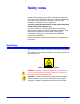
Safety notes Please read the following instructions carefully before planning your install and/or operating the DocuTech 128/155/180 HighLight Color printer. Refer to them as needed to ensure the safe installation and operation of your equipment. The safety testing and performance of this product have been verified using Xerox materials only. Your Xerox DocuTech 128/155/180 HighLight Color printing system and its supplies have been designed and tested to meet strict safety requirements.
S af et y n o te s European Union declaration of conformity Approvals and certification The CE marking applied to this product symbolizes Xerox Europe Declaration of Conformity with the following applicable Directives of the European Union as of the dates indicated below. • January 1, 1995: Council Directive 73/23/EEC amended by Council Directive 93/68/EC, approximation of the laws of the member states related to low voltage equipment.
S af et y no te s Centre for advice prior to any test implementation. The address of the Xerox Technical Centre is provided in the previous section, European Union declaration of conformity. Xerox equipment should, however, be properly and regularly serviced and maintained at all times. Check your understanding Please review the questions and answers that follow to ensure that you understand the Electricity at Work Regulation in England and Wales.
S af et y n o te s ensuring Xerox equipment in such premises is safe. Xerox Europe’s Product Safety function has prepared a guide which contains a list of tests which may be completed by your Xerox Europe Customer Service Organization. THESE TESTS MUST BE CARRIED OUT ONLY BY PERSONS WHO POSSESS THE RELEVANT SKILL, KNOWLEDGE AND EXPERIENCE TO CARRY OUT SUCH TESTS. Please contact the Xerox Europe Customer Service Organization for further information.
S af et y no te s Electrical safety Attention to the following requirements ensures the safe operation of your equipment. Printer USA/Canada Europe The DocuTech 128/155/180 system requires a 208/240 VAC outlet, 4-wire circuit, and has two power cords (one dedicated 30 Amp and one dedicated 50 Amp). The printer requires a 380-415 VAC outlet and one power cord (one dedicated 30 Amp circuit). The equipment must be connected to a grounded main outlet.
S af et y n o te s Controller USA/Canada Europe The controller requires a dedicated 115 VAC 20 Amp grounded receptacle. The controller requires a 220-240V, 13 or 10 Amp grounded receptacle. Controller cautions Follow all safety cautions, warnings, and instructions marked on the controller. • Ensure that the voltages and frequency rating of the power receptacle match the electrical rating label on the equipment. • Do not make electrical or mechanical modifications to the equipment.
S af et y no te s • Any part of the equipment is physically damaged. • The equipment emits unusual odors, or makes unusual noises. NOTE: The only method to remove all power from the printer is to disconnect the power cable from the electrical outlet. If the cable is hardwired to the outlet, the switch or breaker must be used to isolate the power supply from the printer. Printer - ozone information This product produces ozone during normal operation.
S af et y n o te s Printer - operational safety WARNING: Improper connection of the equipment grounding conductor may result in risk of electrical shock. Safety Quality Standards The equipment is manufactured under a BS5750 Quality system accepted by the British Standards Institution. Other National Standards The DocuTech 128/155/180 system is also certified in compliance with applicable standards by various national bodies.
S af et y no te s • Never override or “cheat” any of the electrical or mechanical interlock devices. • Never operate the equipment if you notice unusual noises or odors. Disconnect the power cord from the power outlet and call the Xerox Welcome Center. Your Xerox DocuTech 128/155/180 HighLight Color system is certified, manufactured, and tested in compliance with strict safety and radio frequency interference regulations.
S af et y n o te s xii DocuTech 128/155/180 HighLight Color Installation Planning Guide
1 Introduction The DocuTech 128/155/180 HighLight Color Installation Planning Guide contains information on preparing for the delivery and installation of the DocuTech 128/155/180 HighLight Color printing system. About the printer This product, with its various configurations, is a black plus one color, single-pass spot color printing system. The DocuTech high volume printer configuration is offered in three speeds: 128 ppm, 155 ppm, and 180 ppm.
In tr o d uc t i on • “Safety Notes” explains the various symbols, Cautions, and Warnings pertaining to the safe use and operation of the DocuTech 128/155/180 HighLight Color system. It also contains information on requirements and certifications required by the European Union Declaration of Conformity and the UK Electricity at Work Regulation. • “Planning Responsibilities” provides an overview of the planning process involved when installing a DocuTech 128/ 155/180 HighLight Color printer.
Introduction The features of remote services include: • Always connected – always ON • A common remote support and service workflow that provides a consistent and quality customer support experience • A real-time view of your system status • Improved product development and support • Improved customer productivity For more information, refer to the Remote Services User Guide.
In tr o d uc t i on European Union WARNING: This is a Class A product. In a domestic environment, this product may cause radio interference, in which case the user may be required to take adequate measures. Changes or modifications to this equipment not specifically approved by Xerox Europe may void the user’s authority to operate this equipment. Shielded cables must be used with this equipment to maintain compliance with the EMC Directive (89/336/EEC).
Introduction European Union Some equipment may be used in both a domestic/household and a professional/business application. Domestic/Household Environment Application of this symbol on your equipment is confirmation that you should not dispose of the equipment in the normal household waste stream. In accordance with European legislation end of life electrical and electronic equipment subject to disposal must be segregated from household waste.
In tr o d uc t i on 1- 6 DocuTech 128/155/180 HighLight Color Installation Planning Guide
2 Planning responsibilities This chapter is an overview of the planning process involved when installing a DocuTech 128/155/180 HighLight Color printer. Before installation, you must select and prepare an appropriate location for the printing system and ordered supplies. This chapter helps you accomplish these tasks by providing the following information: • A summary of Xerox responsibilities and your responsibilities. Note that some areas overlap and are joint responsibilities.
Planning responsibilities maintenance. • Assist in resolving hardware and software problems. Customer responsibilities Your responsibilities prior to, during, and after installation of the DocuTech printer are to oversee site personnel, site selection and preparation. Site personnel • Identify a person at your site to be the primary interface with Xerox. Site selection and preparation • Select and prepare the site for the DocuTech printer installation.
Planning responsibilities Table 2-1. Installation planning checklist Week -4 -3 -2 Activity Responsibility Date completed • Select location for the printing system. Customer _________ • Order additional sets of documentation, as necessary. Customer _________ • Register for Xerox Customer Education classes and order tutorials, as necessary. Customer and Xerox _________ • Schedule printer delivery. Xerox • Schedule hardware delivery.
Planning responsibilities Week Install Activity Date completed • Ensure supplies are available. Customer _________ • Ensure system administrators are Customer available during software installation. _________ • Provide applicable completed worksheets from the Getting Ready for the DocuSP Installation document. Customer Install printing system hardware and software. Xerox • Post-install Responsibility _________ _________ • Have operators available for training.
3 Printer components and specifications The printer processes the page images received from the controller and produces the printed output. This chapter describes the printer components and options available for this system.
Printer components and specifications Optionally, up to two additional feeder/stacker middle modules (without the output tray) can be inserted after the inverter feeder/ stacker. Also, an optional Bypass Transport module can be connected to the last feeder/stacker module for transitioning to third party finishing devices. If the Bypass Transport module is attached, then the maximum number of feeder/stackers that can be included in the configuration is two.
Printer components and specifications The print engine is the same as the DT 128/155/180 HLC printer with the inverter feeder/stacker. It also provides control buttons and displays for basic printer functions and status information. Labels are located throughout the printer to assist you with a variety of tasks such as clearing a paper jam. Interposer The 2-tray interposer inserts sheets from Tray 4 to the finisher, bypassing the fuser.
Printer components and specifications 3- 4 DocuTech 128/155/180 HighLight Color Installation Planning Guide
4 Prepare for installation This chapter assists you in selecting a suitable location for installing your DocuTech system. You should consider the following factors when deciding where to place the printer hardware components: • Adequate work space and service clearance around the equipment • Proximity to electrical and network connectors • Security of the work area You may need to place the system in an area where you can restrict access to it.
Prepare for installation • Optional: Printer (HLC module and print engine) + inverter feeder/stacker + 3 feeder/stackers • Optional: Printer (HLC module and print engine) + inverter feeder/stacker + 2 feeder/stackers + bypass transport NOTE: The maximum number of modules allowed in any of the configurations is 4. Measurements and a top-view diagram for each of these configurations is provided on the following pages.
Prepare for installation 744.5 cm 293.1 in. 194.6 cm 76.6 in. 458.5 cm 180.5 in. 91.4 cm 36.0 in. 91.4 cm 36.0 in. 50/60 HZ POWER CORDS * CONTROLLER STAND HLC MODULE PRINTER INTERPOSER FINISHER 91.4 cm 36.0 in. 289.5 cm 114.0 in. 360.6 cm 142.0 in. OPERATOR SIDE 106.7 cm 42.0 in. CONTROLLER STAND 71.1 cm 28.0 in. (OPTIONAL) 71.1 cm 28.0 in. 71.1 cm 28.0 in. 198.4 cm 78.1 in. 351.8 cm 138.5 in. 194.3 cm 76.5 in.
Prepare for installation * The printer depth without the front and rear covers is 34.8 in (88.3 cm) • The space requirements for the controller stand are 30 x 30 in (76.2 x 76.2 cm). • The minimum total space required for this configuration is 264.6 x 142.0 inches (672 cm x 361 cm), including service area. Refer to Figure 4-2. • The total weight of the system is 3129 lbs (1419.3 kgs). NOTE: Not included in this weight is the controller stand or DocuSP controller.
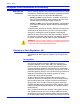
Prepare for installation (4) Printer/HLC with inverter feeder/stacker, two feeder/ stackers and bypass transport The dimensions of the printer with the inverter feeder/stacker, two feeder/stackers and a bypass transport (installed with all front and rear covers) are as follows: Printer HLC Module Inverter feeder/ stacker Feeder/ stacker Bypass transport Width 78 in (198 cm) 23 in (58.4 cm) 42 in (106.6 cm) 32 in (81.2 cm) 20 in (50.8 cm) Depth 42 in (106.6 40 in (101.
Prepare for installation 3 835.0 cm 328.6 in. 2 753.0 cm 296.6 in. 1 672.0 cm 264.6 in. 194.5 cm 78.6 in. 50/60 HZ POWER CORDS 386.0 in. 152.0 in. 91.4 cm 36.0 in. * CONTROLLER STAND HLC MODULE PRINTER IFS FS 91.4 cm 36.0 in. 290.0 cm 114.0 in. 361.0 cm 142.0 in. OPERATOR SIDE 106.7 cm 42.0 in. 71.1 cm 28.0 in. CONTROLLER STAND (OPTIONAL) 71.1 cm 28.0 in. 71.1 cm 28.0 in. 198.4 cm 78.1 in. 279.4 cm 110.0 in. 194.3 cm 76.5 in. 360.7 cm 142.0 in.
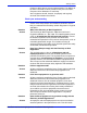
Prepare for installation Space requirements - controller The dimensions for the Controller Stand are 30 inches (76.2 cm) deep and 30 inches (76.2 cm) wide. The operator should have 30 inches (76.2 cm) of space to stand when operating the system from the keyboard. Bypass transport specifications The bypass transport option, which enables you to add a thirdparty finishing device, is available as an external module for the DocuTech 128/155/180 HLC printer.
Prepare for installation Dimensions The following figure shows the dimensions of the bypass transport from the right end view. 440mm /17in Registration edge Sheet path Exit guide 719mm/28in 406mm/16in 20mm /0.8in 334.6mm /13in Front cover 102mm /4in 804mm /31.6 15x33mm /0.6x1.3in 686mm /27in 645.5mm /26in 13.3x33mm /0.5x1.3in 440mm /17in 56mm /2.2in 157.7mm /6.2in Docking bracket Floor Figure 4-3.
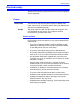
Prepare for installation 2 1 3 106.7 mm/42 in min. service access 4 Input cut sheet Feeder/ stacker Processor Bypass transport Preferred grain direction FRONT 595 mm/23.5 in Feeder/ stacker Out sheet 519 mm /20.5 in 106.7 mm/42 in Hole side Minimum service access 5 6 25 mm/1 in 7 Figure 4-4. Bypass transport space planning diagram (top view) 1. Recommended third-party feeder hardware attaches at the rear of the printer 2. Expected third-party input paper feed path 3.
Prepare for installation Space planning guidelines When determining your space requirements and planning for shared space between your printers, it is important to consider all of the components you plan to install. NOTE: If any doorway or hallway through which the printer is to be moved for delivery is smaller than 37 inches (93 cm), the Rigger and Xerox Service Representative must be present at the time of delivery to disassemble the printer module.
Prepare for installation Shared space between components It is best to provide the full amount of clearance space around the hardware components. Your environment may require you to use shared space between components such as between the printer and the controller or between the printer and another Xerox printing system. You can share the 36-inch (91.4 cm) clearance space around each component, as long as you follow these rules: • Space may be shared only with other Xerox equipment.
Prepare for installation Shared space configuration diagrams for the DT 128/155/180 HLC Printer The following figures illustrate three possible configurations of shared space for the DocuTech 128/155/180 HLC Printer. Back-to-back shared space The figure below illustrates the two printers placed in a back-toback position. This allows the printers to share the entire general service space. 3 835.0 cm 328.6 in. 2 753.0 cm 296.6 in. 1 672.0 cm 264.6 in. 71.1 cm 28.0 in. 71.1 cm 28.0 in. 71.1 cm 28.0 in.
Prepare for installation Front-to-front shared space The following figure shows the two printers facing each other. The printers share the general service space, but not the exclusive operator area in front of each printer. 3 835.0 cm 328.6 in. 2 753.0 cm 296.6 in. 1 672.0 cm 264.6 in. 194.5 cm 76.6 in. 386.0 cm 152.0 in. 91.4 cm 36.0 in. 50/60 HZ POWER CORDS * CONTROLLER STAND HLC MODULE IFS PRINTER FS 91.4 cm 36.0 in. 91.4 cm 36.0 in. 177.8 cm 70.0 in. FS IFS 543.6 cm 214.0 in.
Prepare for installation Front-to-back shared space The following figure shows the two printers arranged with one facing the back of the other. 3 835.0 cm 328.6 in. 2 753.0 cm 1 672.0 cm 264.6 in. 194.5 cm 76.6 in. 296.6 in. 91.4 cm 36.0 in. 386.1 cm 152.1 in. 91.4 cm 36.0 in. 50/60 HZ POWER CORDS 182.9 cm 72.0 in. * CONTROLLER STAND HLC MODULE FS IFS PRINTER OPERATOR SIDE CONTROLLER STAND 177.8 cm 70.0 in. (OPTIONAL) 629.8 cm 248.0 in.
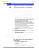
Prepare for installation Shared space configuration diagrams for the DT 180 HLC Production Publisher The following figures illustrate three possible configurations of shared space for the DocuTech 180 HLC Production Publisher. Back-to-back shared space The figure below illustrates the two printers placed in a back-toback position. This allows the printers to share the entire general service space. 744.5 cm 293.1 in. 194.3 cm 76.5 in. 351.8 cm 138.5 in. 198.4 cm 78.1 in. 71.1 cm 28.0 in. 71.1 cm 28.
Prepare for installation Front-to-front shared space The following figure shows the two printers facing each other. The printers share the general service space, but not the exclusive operator area in front of each printer. 744.5 cm 293.1 in. 194.6 cm 76.6 in. 50/60 HZ POWER CORDS 458.5 cm 180.5 in. 91.4 cm 36.0 in. 91.4 cm 36.0 in. * CONTROLLER STAND HLC MODULE PRINTER INTERPOSER FINISHER 91.4 cm 36.0 in. OPERATOR SIDE CONTROLLER STAND 177.8 cm 70.0 in. (OPTIONAL) CONTROLLER 543.6 cm 214.
Prepare for installation Front-to-back shared space The following figure shows the two printers arranged with one facing the back of the other. 744.5 cm 293.1 in. 194.6 cm 76.6 in. 50/60 HZ POWER CORDS 458.5 cm 180.5 in. 91.4 cm 36.0 in. 91.4 cm 36.0 in. * CONTROLLER STAND HLC MODULE PRINTER INTERPOSER FINISHER 360.7 cm 142.0 in. OPERATOR SIDE CONTROLLER 629.8 cm 248.0 in. STAND 177.8 cm 70.0 in.
Prepare for installation Floor leveling For proper operation, the printer must be level. On floors less than two degrees out of level, installation personnel use a leveling kit to level the machine. NOTE: The printer will not function properly on floors more than two degrees out of level. If the floor is more than two degrees out of level, find another location for the printer. For your reference, two degrees represents a height discrepancy of approximately 3.8 inches (9.
Prepare for installation Turning radius You must also consider the width of the passageway when the equipment must negotiate a corner, whether into a room, an elevator, or another passageway. There are L-shaped turns and T-shaped turns. The diagrams and the tables that follow show the minimum space required to maneuver through the turns. Passage A Passage A Figure 4-11. L-shaped and T-shaped turns Using the turning radius tables To use the tables: 1.
Prepare for installation Table 4-1. Turning radius for printer (separated) Passage or doorway A width Minimum passage B width (Cabinet OFF) Minimum passage B width (Cabinet ON) 29 inches / 73.7 cm 74.5 inches / 189.2 cm NA 30 inches / 76.2 cm 64.5 inches / 163.8 cm NA 31 inches / 78.7 cm 62 inches / 157.5 cm NA 32 inches / 81.3 cm 59.5 inches / 151.1 cm NA 34 inches / 86.4 cm 56 inches / 142.2 cm NA 36 inches / 91.4 cm 53 inches / 134.6 cm NA 38 inches / 96.
Prepare for installation Table 4-3. Turning radius for printer (separated and upended on dolly) Passage or doorway A width Minimum passage B width (Cabinet OFF) 42 inches / 106.7 cm 31 inches / 78.7 cm Turning radius for unseparated printer components Minimum passage B width (Cabinet ON) 40.5 inches / 103.0 cm The following table lists the turning requirements for the printer when attached to the paper handling module (not separated). Table 4-4.
Prepare for installation Turning radius for inverter feeder/ stacker module The following table lists the turning requirements for the inverter feeder/stacker module. Table 4-5. Turning radius for inverter feeder/stacker module Passage or doorway A width Minimum passage B width (Cabinet OFF) Minimum passage B width (Cabinet ON) 29 inches / 73.7 cm 43 inches / 109.2 cm NA 30 inches / 76.2 cm 41 inches / 104.1 cm NA 31 inches / 78.7 cm 40 inches / 101.6 cm NA 32 inches / 81.3 cm 38 inches / 96.
Prepare for installation Turning radius for feeder/stacker modules The following table lists the turning requirements for the feeder/ stacker module. Table 4-6. Turning radius for feeder/stacker module Passage or doorway A width Minimum passage B width (Cabinet OFF) Minimum passage B width (Cabinet ON) 29 inches / 73.7 cm 33 inches / 83.8 cm NA 30 inches / 76.2 cm 32 inches / 81.3 cm NA 31 inches / 78.7 cm 31 inches / 78.7 cm NA 32 inches / 81.3 cm 30 inches / 76.2 cm NA 33 inches / 83.
Prepare for installation Printer hardware specifications and requirements summary The following table summarizes the specifications and electrical requirements of your printer hardware components. Table 4-8. Printer specifications and power requirements Device Printer/HLC with interposer and finisher (DT 180 HLC production publisher) Dimensions (width and depth) Total Weight Heat dissipation Power requirements W=203.5 in / 516.8 cm D=42 in / 106.
Prepare for installation Device Printer/HLC with inverter feeder/ stacker and one feeder/ stacker Dimensions (width and depth) Heat dissipation Power requirements 3129 lbs Operating: 32,770 BTU per 1419.3 hr. kg Standby: 4,454 BTU per Total space required (plus hr. access): Energy Saver: 2,700 BTU per 264.6 in (W) x 142.0 in (D) / hr. 672 cm x 361 cm 60 Hz 120/240 VAC or 120/ 208 VAC; 50 amp service; NEMA L1450R; KVA 7.3 (operating) (2 Cords required) Total Weight W=175 in / 444.5 cm D=42 in / 106.
Prepare for installation Device Dimensions (width and depth) Printer/HLC with inverter feeder/ stacker and three feeder/ stackers W=239 in / 607 cm D=42 in / 106.6 cm (with all front and rear covers) Total space required (plus access): 328.6 in (W) x 142.0 in (D) / 835 cm x 361 cm Heat dissipation Power requirements 4171 lbs Operating: 1892 kg 32,770 BTU per hr. Standby: 4,454 BTU per hr. Energy Saver: 2,700 BTU per hr. 60 Hz: 120/240 VAC or 120/ 208 VAC; 50 amp service; NEMA 1450R, KVA 8.
Prepare for installation Power requirements Your printer has important power requirements that must be accommodated. These requirements are summarized in the table below. For further details on power requirements, refer to the voltage charts that follow. Table 4-9. Printer electrical requirements Component Voltage Amp. service KVA rating (operating mode) Printer 60 Hz (U.S.
Prepare for installation 60 Hz printer outlet voltages The following table shows the voltages for the outlets on your printer. All power outlets must have a dedicated circuit for each system equipment piece. Make sure each power cord has a separate circuit. Table 4-10. Printer (60 Hz) voltage requirements at power outlet.
Prepare for installation Service outlet configuration Measurement of wiring Nominal 5 Wire 415 V Line 1 to Line 3 415 V RMS 374-457 V RMS 5 Wire 415 V Line 1 to neutral 240 V RMS 216-264 V RMS 5 Wire 415 V Line 2 to neutral 240 V RMS 216-264 V RMS 5 Wire 415 V Line 3 to neutral 240 V RMS 216-264 V RMS Range Table 4-12. Printer (50 Hz) WYE (Star) 380 and 400 voltage.
Prepare for installation Electrical requirements DocuTech HLC printer The DocuTech HLC printer is produced either as a 50 Hz or 60 Hz unit and is not interchangeable. Power for base accessories comes directly from the printer. The printer can be internally configured to one of the following (local) power distributions: 60Hz (dual power cord) Single service dedicated lines. 3 wires plus ground. Voltage Range is measured at the IOT terminal box.
Prepare for installation Option 2: Two-Phase of a three-phase Branch Circuit (2 lines and neutral, plus ground; total 4-wire system, including ground). Line to neutral: 120 V (nominal); Range 107 V (minimum) to 127 V (maximum) Line to line: 208 V (nominal); Range 185 V (minimum) to 220 V (maximum) Cord 2: 30 amp. per line NEMA 14-30P connector Single service dedicated lines. 3 wires plus ground. Option 1: Single Phase Branch Circuit: (2 lines and neutral, plus ground; total 4 wires, including ground).
Prepare for installation Wye (Star) service Three-Phase Branch Circuit (3 lines and neutral, plus ground; total 5-wire system, including ground). 380/400/415v (220/230/240v per phase); taps set based on actual on-site measurement. 220/380 volts (L-N/L-L) (+/- 10%) 230/400 volts (L-N/L-L) (+/- 10%) 240/415 volts (L-N/L-L) (+/- 10%) Network requirements This section describes the network requirements for installing one or more DocuTech printers.
Prepare for installation that the operator or administrator can easily view the screen and operate the system while remaining on the telephone. Environmental requirements This section describes the environmental requirements for installing one or more DocuTech printers. Temperature, humidity, and altitude specifications When you select a site location for your DocuTech printer, avoid environments with extreme variations in temperature and other hazards, such as excessive dust or humidity.
Prepare for installation Heat management The DocuTech system produces significant amounts of heat when running in a production environment. The heat produced by the system must be considered when selecting a suitable location. Heat management assessment process Consult the site HVAC engineer or contractor to determine whether the heat output can be managed by air conditioning at the site.
Prepare for installation Ordering supplies for the installation You need to order consumable supplies (those that are depleted during operation of the printer), such as paper, dry ink, developer, and fuser blend. It is important that you have an adequate supply on hand for installation and that you maintain the supply after installation. This section describes the supplies needed for installation. Your sales representative will help you place your initial order for supplies.
Prepare for installation Paper is fed into the printer with the long side as the leading edge. When you purchase paper, buy long-grain paper. Make sure the grain is parallel with the long side (long grain) for the most reliable feeding and stacking. Storing paper Paper has a tendency to curl under the heat that is present inside xerographic equipment. To minimize the amount of curling, use paper with low moisture content.
Prepare for installation CAUTION: Fuser lubricant for other printers may not be compatible. Do not use DocuTech 61xx and DocuPrint EPS fuser agent in a DocuTech HighLight Color system. It will contaminate the system. Also, do not use DocuTech HLC fuser blend in other DocuTech or DocuPrint systems. NOTE: For product information, refer to the consumable supplies table in the "Maintenance" chapter.
Prepare for installation 4- 3 8 DocuTech 128/155/180 HighLight Color Installation Planning Guide
5 Installation This chapter describes the activities performed by you and Xerox during the installation of the Xerox DocuTech 128/155/180 HighLight Color hardware and software components. Before installation can begin, you must complete the tasks described in the “Preparing for installation” chapter of this guide. Installation process Xerox is responsible for the physical installation of the DocuTech hardware components and the software.
Installation Your responsibilities Xerox personnel are responsible for the physical installation of the printer components, loading software, configuration and its verification, and Xerox applications. You have the general site responsibility of ensuring that the right personnel, supplies, and network information are available. At the time of installation, you should do the following: • Make sure that your system administrator is available during the loading of software.
Installation Software licensing When your printer is purchased, a license is required to use the operating system software. The host ID is required to obtain the license. This license is enabled by entering an authorization text string at the printer controller keyboard. Your Xerox service representative obtains this license text string for you. Until this license string is entered, while you power on and boot the system, the printer remains in Disabled mode and cannot print.
Installation 5- 4 DocuTech 128/155/180 HighLight Color Installation Planning Guide
6 Maintenance This chapter describes support services available to customers. There is also a description of commonly used consumable supplies and a supplies checklist. Xerox support services Many services are provided in support of your printer. This section contains information on the following services: • Customer Support Center • Customer Education • Supplies Order Service Prior to installation, your sales representative is available to answer your questions about products, services, or billing.
Maintenance The key to effective use of the support center is correct identification of the problem.
Maintenance Your sales representative can help you submit the initial order of supplies needed for installation. These items include paper, dry ink, fuser blend, and developer. Once your printer volume is established, planning ahead and buying Xerox supplies in quantity can save you money. Your supply specialists can help you. NOTE: The supplies resources listed below are for the United States only. Multinational customers should contact their local representatives for supplies ordering information.
Maintenance Routine maintenance There are a number of routine maintenance tasks that must be performed to ensure maximum efficiency of your printer.
Maintenance Table 6-1. Consumable supplies Item Description U.S. part number Paper Xerox paper quantities are 10 reams (5,000 sheets) to a carton unless otherwise noted below 8.5 x 11 inch Xerox Business 4200 Paper 3R2047 A4 Xerox Business 4200 Paper 3R2594 8.5 x 14 inch Xerox Business 4200 Paper 3R2051 11 x 17 inch Xerox Business 4200 Paper 3R3761 8.5 x 11 inch Xerox Business 4200 Paper, 3hole 3R2641 8.5 x 11 inch Dual Purpose Colors, Blue 3R11050 8.
Maintenance Item 6- 6 Description U.S. part number 8.5 x 11 inch Dual Purpose Colors, Gray 3R11057 8.5 x 11 inch Dual Purpose Colors, Gray, 3hole 3R11069 8.5 x 14 inch Dual Purpose Colors, Gray 3R11081 8.5 x 11 inch 10 Series Smooth 3R54 8.5 x 11 inch Xerox Business 4200 Paper, reinforced 3-hole 3R4299 Image LX White 8.5 x 11 inch 3-hole (5000 sheets/carton) 3R11541 Image LX White 8.
Maintenance Item Description U.S. part number Dry Ink Cardinal Red 1 cartridge in Starter Kit; otherwise, 3 cartridges per carton; 300K HLC prints per carton; area coverage is 1.5% 6R1277 Dry Ink Red 1 cartridge in Starter Kit; otherwise, 3 cartridges per carton; 300K HLC prints per carton; area coverage is 1.5% 6R1192 Dry Ink Green 1 cartridge in Starter Kit; otherwise, 3 cartridges per carton; 300K HLC prints per carton ; area coverage is 1.
Maintenance Item Fuser Shield Description Consumption rate is approximately one bottle per 200,000 pages. 1 bottle: 6 bottles: U.S. part number 8R4077 8R7618 Dry ink waste bottle 1 bottle in machine. Capacity is approximately 500,000 impressions per bottle. The Xerox Service Representative maintains the customer supply. 93K1403 HLC developer waste bottle 4 bottles. Capacity is approximately 800,000 highlight color prints at 1.5% area coverage. 604K24870 Stitcher wire Packaged 1 reel per carton.
Maintenance Use the following table to help record the supplies and accessories you require, the date on which the order should be placed, and the actual date of the order. Table 6-2.
Maintenance Item Description Quantity Date of order Date ordered Transparencies Cleaning supplies Other 6- 1 0 DocuTech 128/155/180 HighLight Color Installation Planning Guide