
Instruction Manual


7
FIG.1
ASSEMBLY INSTRUCTION:
1.PREPARATION:
A. Before assembling make sure that you will have enough space around the item.
B. Use the present tooling for assembling.
C. Before assembling please check whether all needed parts are available (at the above
of this instruction sheet you will find an explosion drawing with all single parts (marked
with numbers) which this item consists of.
2.ASSEMBLY INSTRUCTION:
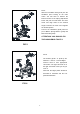
FIG.2
FIG.2:
Slide the Vertical Seat Post (pt.07)
into the seat post housing on the Main
Frame (pt.01). You will have to
slacken the knurled section of the
Knob and pull the knob back and then
select the desired height. Release
the knob and retighten the knurled
portion.
Finally,the Seat (pt.09) fixed on the
Seat Post as shown, and tighten the
nuts under the seat.
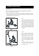
FIG.1:
Attach the Front Stabilizer (pt.55) to the
Main Frame (pt.01) using two sets of
Ø8 Flat Washers (pt.20), M8 Domed
Nut (pt.19) and M8*42 Carriage bolt
(pt.14). Attach the Rear Stabilizer
(pt.57) to the Main Frame (pt.01) using
two sets of Ø8 Flat Washers (pt.20), M8
Domed Nut (pt.19) and M8*42 Carriage
bolt (pt.14).