
User's Guide
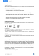
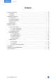
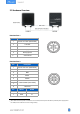
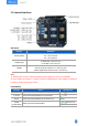
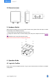
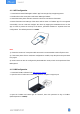
Table Of Contents

6
2.2 Hardware Overview
UC501 UC502
Data Interface 1:
Pin
Description
1
5V/9V/12V OUT (Switchable)
2
3.3V OUT
3
GND
4
Analog Input 1
5
Analog Input 2
6
12
5-24V DC IN
Data Interface 2:
Pin
Description
1
5V/9V/12V OUT (Switchable)
2
3.3V OUT
3
GND
4
GPIO1
5
GPIO2
6
RS232/RS485 (Switchable)
7
8
Reserved
Pin
RS232
RS485
6
TXD
A
7
RXD
B
1
When both DC external power and batteries are connected, external power will be the preferred power supply option.
2
For UC502, the DC interface can’t be to charge battery.