Outdoor LoRaWAN® Gateway UG67 Quick Start Guide Milesight IoT
Safety Precautions Milesight will not shoulder responsibility for any loss or damage resulting from not following the instructions of this operating guide. The device must not be modeled in any way. Do not place the device close to objects with naked flames. Do not place the device where the temperature is below/above the operating range. Do not power on the device or connect it to other electrical device when installing. Check lightning and water protection when used outdoors.
(2) This device must accept any interference received, including interference that may cause undesired operation. Note: This equipment has been tested and found to comply with the limits for a Class B digital device, pursuant to part 15 of the FCC Rules. These limits are designed to provide reasonable protection against harmful interference in a residential installation.
Contents 1. Packing List....................................................................................................................................................5 2. Hardware Introduction................................................................................................................................. 6 2.1 Overview...............................................................................................................................................6 2.2 Dimensions (mm)......
1. Packing List Before you begin to install the UG67 LoRaWAN® Gateway, please check the package contents to verify that you have received the items below. 1 × UG67 1 × PoE Injector 1 × Cable Gland 1 × Warranty Card 1 × Mounting Bracket Wall Mounting Kits 1 × SIM Dust Cover 2 × Hose Clamps 1 × DC Power Cable 1 × Quick Start Guide 2 × LoRa Antennas 1 × Antenna Coaxial Cable (1m) 1 × Antenna Clamp Kit If any of the above items is missing or damaged, please contact your sales representative.
2. Hardware Introduction 2.1 Overview LoRa Antenna Connector 2 Vent Plug 3 SIM Slot 4 LED Area & Type-C Port & Reset Button SYS: System Indicator LoRa: LoRa Indicator LTE: Cellular Indicator 1 5 6 7 DC Power Connector (Solar Connector) Ethernet Port (PoE) Mounting Bracket 2.2 Dimensions (mm) 2.
Blinking rapidly: SIM card has been registered and is dialing up now Static: SIM card has been registered and dialed up successfully 2.4 Reset Button Function Reset Description SYS LED Action Static Green Press and hold the reset button for more than 5 seconds. Static Green → Rapidly Blinking Release the button and wait. Off → Static Green The gateway resets to factory default. 2.5 DC Power Connector UG67 supports 12 VDC or solar supply via M12 connector.
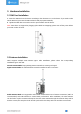
3. Hardware Installation 3.1 SIM Card Installation A. Insert the SIM card into the device according to the direction icon on the device. If you need to take out the SIM card, press into the SIM card and it will pop up automatically. B. Tighten the SIM dust cover with wrench to prevent water into the device. Note: UG67 does not support hot plugging (also called hot swapping). please turn off the power before you insert or take off cards. 3.2 Antenna Installation UG67 supports multiple LoRa antenna types.
3.3 Ethernet Cable & Power Cable Installation Pass the Ethernet cable through the cable gland and rotate the cable gland to gateway, then tighten the cable gland with wrench. For DC or solar power supply, remove the protective cap of power connector and rotate the DC power cable into the power connector. 3.4 Power Supply UG67 can be powered by 802.3af standard PoE or 12VDC.
3.5 Gateway Installation UG67 can be mounted to a wall or a pole. Before you start, make sure that your SIM card has been inserted, your antennas have been attached and all cables have been installed. Note: Do not connect device to power supply or other devices when installing. 3.5.1 Wall Mounting Preparation: mounting bracket (with a screw), wall plugs, wall mounting screws and other required tools. A.
3.5.2 Pole Mounting Preparation: mounting bracket (with a screw), hose clamp and other required tools. A. Loosen the hose clamp by turning the locking mechanism counter-clockwise. B. Straighten out the hose clamp and slide it through the rectangular rings in the mounting bracket, wrap the hose clamp around the pole. C. Use a screwdriver to tighten the locking mechanism by turning it clockwise. D.
4. Login the Web GUI UG67 provides web-based configuration interface for management. If this is the first time you configure the gateway, please use the default settings below: ETH IP Address: 192.168.23.150 Wi-Fi IP Address: 192.168.1.1 Wi-Fi SSID: Gateway_****** Username: admin Password: password 4.1 Wireless Access A. Enable Wireless Network Connection on your computer and search for access point “Gateway_******” to connect it. B.
E. You can view system information and perform configuration of the gateway. 4.2 Wired Access Connect PC to UG67 ETH port through PoE injector. The following steps are based on Windows 10 operating system for your reference. A. Go to “Control Panel” → “Network and Internet” → “Network and Sharing Center”, then click “Ethernet” (May have different names). B.
C. Open a Web browser on your PC (Chrome is recommended) and type in the IP address 192.168.23.1 50 to access the web GUI. D. Enter the username and password, click “Login”. If you enter the username or password incorrectly more than 5 times, the login page will be locked for 10 minutes. E. After logging the web GUI, follow the guide to complete the basic configurations. You can also skip the instructions. It’s suggested that you change the password for the sake of security. F.
5. Network Connection This section explains how to connect the gateway to network via WAN connection, Wi-Fi or cellular. 5.1 Configure the Ethernet Connection A. Go to “Network”→ “Interface” → “Port” page to select the connection type and configure Ethernet port information. B. Click “Save & Apply” for changes to take effect. C. Connect Ethernet port of gateway to devices like router or modem. D. Log in the web GUI via the newly assigned Ethernet port IP address and check network connection. 5.
C. Type the key of Wi-Fi. D. Go to “Status”→”WLAN” to check Wi-Fi status. If it shows “Connected”, it means gateway connects to Wi-Fi successfully.
5.3 Configure the Cellular Connection A. Go to “Network” → “Interface” → “Cellular” → “Cellular Setting” page to enable cellular settings. B. Choose relevant network type and fill in SIM card information like APN or PIN code. C. Click “Save” and “Apply” for changes to take effect. D. Go to “Status” → “Cellular” page to view the status of the cellular connection. If it shows “Connected”, it means the SIM has dialed up successfully. On the other hand, you can check the status of LTE indicator.
6. Packet Forwarder Configuration UG67 has installed multiple packet forwarders including Semtech, Chirpstack-Generic MQTT broker, etc. This section explains how to connect the gateway to network servers. Make sure the gateway connects to the network as shown in Section 5. A. Go to “Packet Forwarder” → “General” page and click to add a network server. B. Fill in the server information and enable this server. C.
D. Add the gateway on network server page. For more details about the network server connection please refer to Milesight IoT Support portal. E. Go to “Traffic” page to view the data communication of UG67.
7. Network Server Configuration UG67 can work as network server and transmit data to Milesight IoT Cloud or other platform via MQTT/HTTP/HTTPS. Make sure the gateway connects to the network as shown in Section 5. 7.1 Connect UG67 to Milesight IoT Cloud A. Go to “Packet Forwarder” → “General” page to enable the embedded network server. B. Go to “Packet Forwarder” → “Radio” page to select the antenna type, center frequency and channels. The channels of the gateway and nodes need to be the same. C.
D. Log in the Milesight IoT Cloud. Then go to “My Devices” page and click “+New Devices” to add gateway to Milesight IoT Cloud via SN. Gateway will be added under “Gateways” menu. E. The gateway is online on Milesight IoT Cloud.
7.2 Connect UG67 to MQTT/HTTP Server A. Go to “Packet Forwarder” → “General” page to enable the embedded network server. B. Go to “Packet Forwarder” → “Radio” page to select the antenna type, center frequency and channels. The channels of the gateway and nodes need to be the same. C. Go to “Network Server” → “General” page to enable the network server mode.
D. Go to “Network Server”→”Application” to add a new application. After saving the application, you can select HTTP, HTTPS or MQTT protocol and fill in correspond server information to send data to another server. E. Go to “Profiles” page to add a new profile for the device.
F. Go to “Device” page and click “Add” to add LoRaWAN® node devices. You can also click “Bulk Import” if you want to add many nodes all at once. Click “Template Download” to download template file and add device information to this file.
and device profile should be the same as you created on web page. Import this file to add bulks of devices. F. Go to “Packets” page to check the packets from LoRaWAN® node devices. The type starts from “Up” means uplinks and “Dn” means downlinks. Click “Details” to check the properties and payload contents of packets.