
User's Manual

Identification of Controls
5
39 10
11
12
13
7
15
14
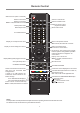
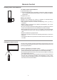
1. :Switch the screen power on or standby.
2. : Press the button to display input source menu or
exit the menu screen.
3. : Press the button to return to previous menu.
4. : Press the button to display desktop (Home page)
on the screen.
5. : Press the button to open the setting menu.
6. : Press the button to turn down the volume.
7. : Press the button to turn up the volume.
8. : USB for IFP.(Android)
9. : USB for OPS.
Note: If no OPS insterted, the USB port has no function.
10.USB(2.0)(for camera): This port is connected to PC
when current source is PC (internal OPS) , but is
changed to Android if current source is AV, USB or
in Home page.
Note: Please open the dust cover before being used.
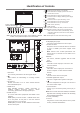
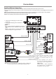
1.VGA OUT
The currently selected PC IN 1/2/3 signal output.
2.
WIFI antenna for transmitting or receiving network
signal.
3.PC IN1/2/3
Enable connection to PC or other external devices
with VGA/AUDIO ports.
4.USB2.0/3.0
USB standard interface, enable connection to
USB2.0, USB3.0 standard devices. When
connecting, please select the appropriate port.
5.HDMI1/2 Input
To connect with those equipments with HDMI or DVI
interface.
HDMI1(MHL): Connect an MHL - enabled device such
as a cell phone to this jack to view the external
device’s screen on your screen.
HDMI2(ARC): Connect an ARC-enabled home theater
receiver to this jack.
6. DP(DisplayPort) Input
Connect an external device to DP out jack.
7.TOUCH1/2 OUT
Output the touch for external devices connected
to PCx or HDMIx port which support touch
system.
Note: TOUCH OUT 2 takes precedence over
TOUCH OUT 1 in default. You can define it to in
Lock menu.
8.RS232
For service, software upgrades and the other
uses.
9.WAN IN
The built-in router input port. Connect to the
external network.
10.LAN OUT
The built-in router output port. Connection to
another computer or other Internet enabled
devices.
11.AV IN
Connect an AV device to this jack.
12.S/PDIF digital audio output
Connect a digital sound system to this jack.
13.
Connect headphones to this jack. The screen is
the current audio output.
14. Power Switch
Push to (1) to connect the power, push to (O ) to
cut off.
Note:
15. Fuse (12A 250V)
16. AC IN
Plug the AC cord into this jack and into a power
outlet.(~100-240V 50Hz/60Hz)
Do not cover the Power switch, it should be
kept free from coverings so that it can be easily
and conveniently operated.
1
2
3
4
5
6
4
7
8
16
HDMI 1
(MHL)
HDMI 2
(ARC)
VGA 1
PC IN 1
VGA 2
PC IN 2
TOUCH
OUT 1
AUDIO
TOUCH
OUT 2
2
Note: T
c .
he position of the key and port may be different of different
models, orrect positions depend on the actual model
Remote Sensor
Power Indicator
1 2 3 4 5 6 7 8 9
10