
Product Description


Xiaomi Communications Co., Ltd.
14 / 14
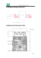
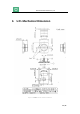
Module design considerations
The module is recommended to be placed at the corner of the plate, and the antenna is facing outwards.
Keep a clearance of at least 15mm around the antenna. Keep it away from metal devices, sensors, high-
frequency signal transmission devices, and high-frequency signal traces. Increase the distance from the
location to the interference. The source energy is attenuated with increasing distance, which reduces the
coupling of noise and improves the overall performance of the antenna.
The recommended output current of the power chip selected for the module power supply is at least 500mA.
It is recommended that the module should be powered by an independent power supply.
Do not allow any object to interfere with the antenna.
It is forbidden to route under the PCB antenna and do clearance processing. It is recommended that the width
of the slot under the antenna with the mother board is at least 5mm from the edge of the antenna board.
All the power supply interfaces and pull-up power supply of the module, please use the same power network
to ensure that the power on sequence of the module is consistent.
Power supply ripple requirements for the module: When sending 11n MCS7 packets, the power ripple must
be less than 100mV; when sending 11b / 11g packets, the power ripple must be less than 120mV.
When communicating between the module and the CPU through SDIO and UART, it is best to connect a 200
ohm resistor in series on the signal line (resistance value can be adjusted according to actual needs) to reduce
the driving current and interference, and also eliminate Timing problems caused by inconsistent line lengths.
Avoid high-speed signals around and below the module. If you cannot avoid them, it is recommended to
strictly follow the high-frequency signal processing rules to try to cover the high-speed signals with ground
as much as possible. When data or addr lines are involved, packaged in groups to cover with grounds.
If high-power devices such as motors are involved in the system design, the circuit return path (GND) of the
module must be separated from the return paths (GND) of other high-power devices, and finally connect the
two return paths ( GND) with a wire.
When selecting the module, try not to use the PCB on-board antenna, because the PCB on-board antenna is
interfaced more interferences, and it is easy to couple interference sources to affect the performance of the
antenna. It is best to use an external antenna, which can be led out of the PCB through the cable Board, so
the influence of high frequency interference signals on the antenna performance of the module will be
reduced.
After the product design is completed, it is recommended to test the antenna performance of the whole
machine according to the product definition to confirm whether the antenna performance meets the
requirements of the whole machine.
Module reference design circuit, please refer to the module schematic diagram.