
Inc. Bus Analyzer Product Specification

ChipScope PLBv46 IBA (Bus Analyzer) (v1.00a)
DS619 (v1.0) September 17, 2007 www.xilinx.com
Product Specification 5
R
a user to look for multiple occurrences of the match event.
This counter width is controllable through the
C_MU_xx_CNT_W parameter (xx is a place holder for
1-13). When this parameter is set to 0 only 1 occurrence is
counted, otherwise the match event count is limited by the
width of this parameter.
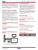
The number of match units to use is defined by the
C_MU_xx_NUM parameter. By default if a match unit does
not have the C_MU_xx_NUM parameter then only one
match unit is used for the match group. If the
C_MU_xx_NUM parameter is defined, then one or two
match units are available for this match group. What this
enables is looking at sequences of this particular match
group. For instance in match group 2 you may want a trigger
sequence to first look at PLB_PAValid=1 followed by a rising
edge on PLB_SaddrAck. For this specific trigger the first
match unit is set to look for PLB_PAValid=1 and the second
is set for PLB_SaddrAck=R.
The first match unit is labeled 1a and 1b. The 1a group of
signals makes up the reset and error flag signals. The 1b
group contains master related error signals. The generator
allows adding 1a, 1b or both of these groups to the core via
the generic parameters C_USE_MU_1A, and
C_USE_MU_1B respectively.
The second match unit has labels 2a, 2b, and 2c. The 2a
signals contain 16 of the primitive ports which provide
essential PLB bus transaction information. The 2b signals
contain buses that identify widths and master information of
the active transaction. The 2c label is used for the
transaction attribute bus. The three subdivided match unit
groups can be all or individually enabled using the
parameters C_USE_MU_2A, C_USE_MU_2B, and
C_USE_MU_2C.
The third, fourth, and fifth match units are used for the
address, data write, and data read buses respectively. Each
bus has a dedicated match unit so it can be individually
enabled and defined with unique C_MU_xx_TYPE pattern
match units.
The 6a and 6b match units are used for the slave side
interface. This match unit holds all the control and status
ports of all the slaves on the PLB. Similarly, match units 11,
12 and 13 have all the control and status of all the masters.
Note:
When these match units are enabled, all slaves or masters
are enabled. You cannot individually enable a particular master.
The match units 7, 8, and 9 are slave side signals for BUSY,
READ, and WRITE error controls going to the master.
These units are broken out individually because this bus
has one signal for each master on each slave.
Consequently, you can have up to 256 signals on each one
of these match units (if PLB goes to a 16 slave, 16 master
solution).
The arbiter status signals can be monitored using match
unit 10. The signals probed by this match unit can help
identify the order of the PLB master transactions that are
being sorted on the bus.
ChipScope PLB46 IBA Parameters
To create a ChipScope PLB46 IBA uniquely tailored for your
system and to optimize performance, specific features can
be parameterized on the PLB IBA. Ta ble 2 describes the
features that can be parameterized.
The ChipScope PLB IBA peripheral supports multiple
trigger units that connect to the PLB Control bus, Address
bus, Data bus, lumped Slave or Master busses. Each one of
these trigger units can be enabled and parameterized
independently. Ta b l e 2 lists all the parameters used in
selecting the trigger port connections. These parameters
define what signals are connected to the trigger ports, the
match unit type, and if the signals are stored in the sample
buffer.
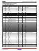
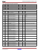
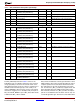
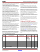
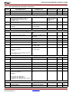
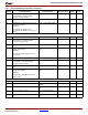
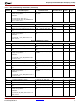
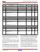
Tabl e 2 : IBA_PLBv46 Design Parameters
Generic Feature/Description Parameter Name Allowable Values
Default
Value
VHDL
Type
G1 Target Family C_FAMILY Spartan3,
Spartan3E,
Spartan3A,
Spartan3ADSP,
Spartan3AN,
Virtex, VirtexE,
Virtex4, Virtex5
Virtex5 String
G2 Device C_DEVICE String
G3 Device Package C_PACKAGE String
G4 Device speed grade C_SPEEDGRADE String
G5 Number of PLB Masters C_PLBV46_NUM_MASTERS 1-8 2 Integer
G6 Number of PLB Slaves C_PLBV46_NUM_SLAVES 1-8 1 Integer
G7 Number of bits required to encode the
number of PLB Masters
C_PLBV46_MID_WIDTH 1-5 2 Integer