
User manual

14 www.xilinx.com Virtex-II Prototype Platform
1-800-255-7778 UG015 / PN0401974 (v1.1) January 14, 2003
R
Detailed Description
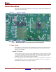
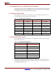
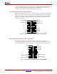
The Virtex-II Prototype Platform board is shown in Figure 2. Each feature is detailed in the
numbered sections that follow.
1. Power Switch
The board has an on-board power supply and a three-position power switch: upward on,
off, and downward on. When lit, a green LED indicates power to the device core when
V
CCINT
is 1.5V or higher.
Upward On Position
In the upward on position, the power switch enables delivery of all power to the board by
way of voltage regulators situated on the backside of the board. These regulators feed off
an external power brick with a voltage range from 5-14V. Special circuitry delivers the
required power to the Service FPGA and Service PROM.
The voltage regulators deliver fixed voltages; however, you can adjust these voltages by
changing the settings on the dip switch site marked ADJUST (1a) as shown in Figure 2.
Maximum current range for each supply is 500 mA.
Figure 2: Detailed Description of Virtex-II Prototype Platform Components
1
1a
11
10
3
2
4
8
18
9
5
6
7
17
5a 5c
12
19
13
14
22
23
24
25
15
21
16
20
5b 5d