
User manual

16 www.xilinx.com Virtex-II Prototype Platform
1-800-255-7778 UG015 / PN0401974 (v1.1) January 14, 2003
R
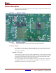
3. Configuration Port User PROM and FPGA Header
This header is used to connect a MultiLINX cable or Parallel Cable III cable to the board
and supports all Virtex-II device configuration modes. (See Table 4 for connecting cables to
the Configuration Port User PROM and FPGA header.)
4. Frequency Select Switch
The frequency select switch sets the frequency of the on-board clock generator. One of
sixteen frequencies can be selected as shown in Table 2.
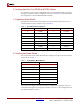
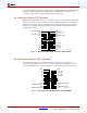
5. Configuration Mode Switch
The configuration mode switch determines the configuration mode of the DUT using the
options shown in Table 3.
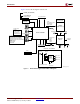
In master serial configuration modes, the DUT is configured from either the on-board
serial PROM, the Upstream Configuration Interface connector, or the Configuration Port
User PROM and FPGA header.
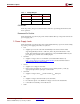
Table 2: Clock Generator Frequencies
Switch Position Clock Frequency Switch Position Clock Frequency
025 MHz862.5 MHz
130 MHz966 MHz
2 33 MHz A 67.5 MHz
340 MHzB70 MHz
4 45 MHz C 77.5 MHz
550 MHzD80 MHz
655 MHzE83 MHz
760 MHzF90 MHz
Table 3: Configuration Mode Options
Switch Position Mode Label
0 MSTR SERIAL PROM
1 MSTR SERIAL UPSTRM
2 MSTR SEL MAP PROM
3 MSTR SEL MAP UPSTRM
4SLAVE SERIAL
5JTAG
6 SELECT MAP
7EXTERNAL