
User manual

20 www.xilinx.com Virtex-II Prototype Platform
1-800-255-7778 UG015 / PN0401974 (v1.1) January 14, 2003
R
must be provided by the user. The only services provided by the board in this mode are the
on-board oscillators, the DONE and INIT LEDs, and VBATT. All connections to the
configuration pins must be made using the breakout test points.
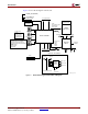
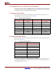
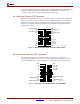
5a. Upstream System ACE Connector
The Upstream System ACE connector, as shown in Figure 3, can be used to configure the
DUT. This connector can be sourced by any JTAG configuration stream. For example, a
System ACE Controller with CompactFlash can be used to generate very large JTAG
streams for configuring multiple Virtex-II Prototype Platforms using the Downstream
System ACE connector.
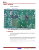
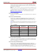
5b. Downstream System ACE Connector
The Downstream System ACE connector, as shown in Figure 4, is used to pass
configuration information to a DUT in a downstream prototype platform from sources
such as a MultiLINX cable, Parallel Cable III, or an Upstream System ACE connector.
Figure 3: Upstream System ACE Connector, 20-Pin Female
UG015_03_061401
NC
UPSTREAM_TMS
GND
UPSTREAM_TDI
GND
V5
GND
UPSTREAM_TCK
GND
UPSTREAM_TDO
GND
VCC3_EN
VCC3_EN
VCC3_EN
VCC3_EN
V5
V5
V5
V5
GND
135791113151719
2468101214161820
Figure 4: Downstream System ACE Connector, 20-Pin Male
UG015_04_061401
DOWNSTREAM_TDO
GND
DOWNSTREAM_TCK
GND
V5
NC
DOWNSTREAM_TMS
GND
DOWNSTREAM_TDI
GND
GND
V5
V5
V5
V5
VCC3_EN
VCC3_EN
VCC3_EN
VCC3_EN
GND
135791113151719
2468101214161820