
User manual

Virtex-II Prototype Platform www.xilinx.com 23
UG015 / PN0401974 (v1.1) January 14, 2003 1-800-255-7778
Detailed Description
R
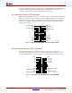
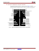
7. Chip Select Switch
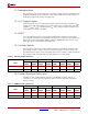
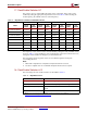
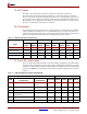
The chip select switch assigns a unique identification (ID) to each DUT in a select map
configuration chain. This switch may be set from 0 to 3, allowing up to four devices to be
configured/read back in a select map chain. During readback, each board in the chain
must have a unique ID, otherwise more than one device will drive the data bus. However,
multiple DUTs may be set to the same ID for “Select Map Mode” configuration. Pins on the
configuration connectors correspond to each ID. The CS pin on the DUT will be connected
to the CS pin on the configuration connector that corresponds to its chip select switch.
The CS pin on the DUT is set to zero, by default, when the configuration mode is set to
Master Select Map PROM. Otherwise, its value is dependent on the value of the
UPSTREAM_CS[3:0] pins.
8. User PROM Socket
The user PROM socket can be used to configure the Virtex-II device in master serial mode.
The socket accepts XC17V01-V04 and XC18V01-V04 series configuration PROMs in VQ44
packages. The PROM port can also be used to reprogram the PROM using JTAG. (Consult
the Xilinx data book, http://www.xilinx.com/partinfo/databook.htm
, for selecting the
appropriate PROM device for each particular Virtex-II device.)
9. JTAG Interface, Service PROM, and FPGA Header
In addition to the user PROM, the board has a dedicated XC18V01 serial PROM that
configures the Service FPGA. The Service PROM and the Service FPGA are not part of the
user configuration chain. Only the DUT and its related configuration PROM are part of the
configuration chain.
Warning!
Do not use the JTAG Interface Service PROM and FPGA header. This can cause the
board to malfunction. This header is for internal use only.
10. PROM Daughter Card Interface
This header is located near the User PROM socket so that the PROM may be substituted
with a daughter board, permitting daisy-chaining of PROMs and experimentation with
other configuration methods.
Note:
PROM substitution is dependent upon configuration and JTAG switch settings.
11. Service FPGA
In addition to the DUT FPGA, the board contains a Service FPGA. The Service FPGA acts
as a switch matrix to control the routing of all of the configuration signals on the board.
This enables simple rotary switches (rather than jumpers) to control the board, minimizing
training and errors. The Service FPGA is configured by a dedicated Service PROM. The
Service FPGA and the Service PROM are not part of the user configuration chain. Only the
DUT and its related configuration PROM are part of the configuration chain.
Warning!
Do not use the JTAG Interface Service PROM and FPGA header. This can cause the
board to malfunction. This header is for internal use only.