
User manual

Virtex-II Prototype Platform www.xilinx.com 27
UG015 / PN0401974 (v1.1) January 14, 2003 1-800-255-7778
Detailed Description
R
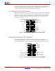
22. Program Switch
The active-low program switch, when pressed, grounds the program pin on the DUT. This
switch is driven indirectly by the Service FPGA.
23. Reset Switch (Active-Low)
The reset switch connects (indirectly through the Service FPGA) to the INIT pin on the
DUT, allowing the user, after configuration, to reset the logic within the DUT. Before and
during configuration of the DUT, the INIT pin has no function. After configuration, the
INIT pin becomes a regular I/O. When pressed, this switch grounds the INIT pin.
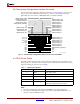
24. DONE LED
The DONE LED indicates the status of the DONE pin on the DUT. This LED lights when
DONE is high or if power is applied to the board without a part in the socket.
25. INIT LED
The INIT LED lights during initialization.
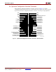
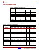
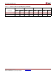
LED 6 Select Map D6 R4 AB4 AD6 AG24
LED 7 DLL Locked Status D7 P4 AA4 AC6 AG25
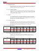
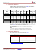
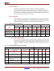
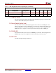
Table 13: LED Assignments and Corresponding I/O (Continued)
Configuration Mode Status Pin Number For Package Type
LED
Before and During
Configuration
After
Configuration
Status Pin FG256 FG456 FG676 FF1152