LogiCORE™ IP SPI-4.2 Core v8.
R "Xilinx" and the Xilinx logo shown above are registered trademarks of Xilinx, Inc. Any rights not expressly granted herein are reserved. CoolRunner, RocketChips, Rocket IP, Spartan, StateBENCH, StateCAD, Virtex, XACT, XC2064, XC3090, XC4005, and XC5210 are registered trademarks of Xilinx, Inc. The shadow X shown above is a trademark of Xilinx, Inc. ACE Controller, ACE Flash, A.K.A.
Revision History The following table shows the revision history for this document. Date Version Revision 09/30/04 1.0 Initial Xilinx release. 11/11/04 1.1 Document updated to support SPI-4.2 core v7.1. 04/28/05 1.2 Document updated to support SPI-4.2 core v7.2 and Xilinx ISE v7.1i. 08/31/05 2.0 Updated ISE service pack information. 1/18/06 3.0 Updated ISE to v8.1i, release date 7/13/06 4.0 Added support for Virtex-5, ISE to v8.2i, advanced version number and release date. 9/21/06 4.
SPI-4.2 v8.5 Getting Started Guide UG154 March 24, 2008 www.xilinx.
Table of Contents Schedule of Figures . . . . . . . . . . . . . . . . . . . . . . . . . . . . . . . . . . . . . . . . . . . . . . . . . . . . . . . . . . 7 Schedule of Tables . . . . . . . . . . . . . . . . . . . . . . . . . . . . . . . . . . . . . . . . . . . . . . . . . . . . . . . . . . . 9 Preface: About This Guide Contents . . . . . . . . . . . . . . . . . . . . . . . . . . . . . . . . . . . . . . . . . . . . . . . . . . . . . . . . . . . . . . . . . . . . 11 Conventions . . . . . . . . . . . . . .
R / . . . . . . . . . . . . . . . . . . . . . . . . . . . . . . . . . . . . /doc . . . . . . . . . . . . . . . . . . . . . . . . . . . . . . . . . . . . . . . . . . . . . . . . . . /example design . . . . . . . . . . . . . . . . . . . . . . . . . . . . . . . . . . . . . . . . /implement . . . . . . . . . . . . . . . . . . . . . . . . . . . . . . . . . . . . . . . . . . . . implement/results . . . . . . . . . . . . . . . . .
Schedule of Figures Chapter 3: Quick Start Example Design Figure 3-1: Core Customization GUI Main Window. . . . . . . . . . . . . . . . . . . . . . . . . . . . . . . 20 Chapter 4: Detailed Example Design Figure 4-1: Example Design Configuration. . . . . . . . . . . . . . . . . . . . . . . . . . . . . . . . . . . . . . . 33 Figure 4-2: Demonstration Test Bench Connections . . . . . . . . . . . . . . . . . . . . . . . . . . . . . . . 34 Figure 4-3: Test Bench Modules . . . . . . . . . . . . . . . . . . . . .
R www.xilinx.com SPI-4.2 v8.
Schedule of Tables Chapter 4: Detailed Example Design Table 4-1: Project Directory. . . . . . . . . . . . . . . . . . . . . . . . . . . . . . . . . . . . . . . . . . . . . . . . . . . . . 26 Table 4-2: Component Name Directory . . . . . . . . . . . . . . . . . . . . . . . . . . . . . . . . . . . . . . . . . . 26 Table 4-3: Doc Directory . . . . . . . . . . . . . . . . . . . . . . . . . . . . . . . . . . . . . . . . . . . . . . . . . . . . . . . 26 Table 4-4: Example Design Directory . . . . . . . . . . . .
R www.xilinx.com SPI-4.2 v8.
R Preface About This Guide This guide provides information about generating the Xilinx LogiCORE™ IP SPI-4.2 core, customizing and simulating the core using the provided example design, and running the design files through implementation using the Xilinx tools. Contents This guide contains the following chapters: • Preface, “About this Guide” introduces the organization and purpose of the Getting Started Guide, and the conventions used in this document.
R Preface: About This Guide Typographical The following typographical conventions are used in this document: Convention Meaning or Use Example Courier font Messages, prompts, and program files that the system displays speed grade: - 100 Courier bold Literal commands that you enter in a syntactical statement ngdbuild design_name References to other manuals See the Development System Reference Guide for more information.
R Chapter 1 Introduction The LogiCORE IP SPI-4.2 (PL4) core is a fully verified design solution that supports Verilog and VHDL. The example design in this guide is provided in both Verilog and VHDL. This chapter introduces the SPI-4.2 core and provides related information, including recommended design experience, additional resources, technical support, and how to submit feedback to Xilinx.
R Chapter 1: Introduction Contact your local Xilinx representative for a closer review and estimate of the effort required to meet your specific design requirements. Additional Core Resources For detailed information and updates about the SPI-4.2 core, see the following additional documents located on the SPI-4.2 product page. • LogiCORE SPI-4.2 Data Sheet • LogiCORE SPI-4.2 Release Notes • LogiCORE SPI-4.2 User Guide For updates to this document, see the LogiCORE SPI-4.
R Chapter 2 Licensing the Core This chapter provides instructions for obtaining a license for the core so that you can use the core in a design. The SPI-4.2 core is provided under the terms of the Xilinx LogiCORE Site License Agreement. This license agreement conforms to the terms of the SignOnce IP License standard defined by the Common License Consortium. Purchase of the core entitles you to technical support and access to updates for a period of one year.
R Chapter 2: Licensing the Core be tested in the target device for a limited time before timing out. The core can be reactivated by reconfiguring the device after a time out.
R Installing Your License File Follow the instructions in the lounge to fill out the license request form; then click Submit to automatically generate the license. An email containing the license and installation instructions will be sent to you immediately. Installing Your License File After selecting a license option, an email is sent to your login account that includes instructions for installing your license file.
R 18 Chapter 2: Licensing the Core www.xilinx.com SPI-4.2 v8.
R Chapter 3 Quick Start Example Design The quick start steps provide information to quickly generate a SPI-4.2 core, run the design through implementation with the Xilinx tools, and simulate the example design using the provided demonstration test bench. For more detailed information about this example design, see Chapter 4, “Detailed Example Design.” Overview The SPI-4.2 example design consists of the following: • SPI-4.2 Sink and Source core netlists • SPI-4.
R Chapter 3: Quick Start Example Design 5. After creating the project, locate the directory containing the SPI-4.2 core in the taxonomy tree; it appears under Communications & Networking > Telecommunications > SPI-4.2. 6. Double-click the core to bring up the customization GUI. 7. In the Component Name field, enter a name for the core instance. (In this example, the name quickstart is used.) 8. After selecting the desired features and parameters from the GUI screens, click Generate.
R Implementing the Example Design Implementing the Example Design After generating a core with a Full System Hardware Evaluation or Full license, the netlists and the example design can be processed by the Xilinx implementation tools. The generated output files include scripts to assist you in running the Xilinx tools. To implement the SPI-4.2 example design, open a command prompt or terminal window and type the following commands: For Windows ms-dos> cd \\implement ms-dos> implement.
R Chapter 3: Quick Start Example Design To run a VHDL or Verilog functional simulation of the example design using NCSIM: 1. Set the current directory to: /simulation/functional/ 2. Execute the simulation script: % simulate_ncsim.sh ms-dos> simulate_ncsim.bat To run a Verilog functional simulation of the example design using VCS: 1. Set the current directory to: /simulation/functional/ 2. Execute the simulation script: % simulate vcs.
R Running the Simulation The simulation script compiles the timing simulation model and the demonstration test bench, adds relevant signals to the wave window, and runs the simulation. To observe the operation of the core, inspect the simulation transcript and the waveform. SPI-4.2 v8.5 Getting Started Guide UG154 March 24, 2008 www.xilinx.
R 24 Chapter 3: Quick Start Example Design www.xilinx.com SPI-4.2 v8.
R Chapter 4 Detailed Example Design This chapter provides detailed information about the example design, including a description of files and the directory structure generated by the Xilinx CORE Generator, the purpose and contents of the provided scripts, the contents of the example HDL wrappers, and the operation of the demonstration test bench.
R Chapter 4: Detailed Example Design Directory and File Contents The SPI-4.2 core directories and their associated files are defined in the following sections. The project directory contains all the CORE Generator project files. See the SPI-4.2 User Guide for detailed information about each file. Table 4-1: Project Directory Name Description _pl4_snk_top.ngc _pl4_src_top.ngc Top-level netlists. _pl4_snk_top.
R Directory and File Contents Table 4-3: Doc Directory (Continued) Name Description SPI-4.2 User Guide spi4_2_ug153.pdf Back to Top /example design The example design directory contains the example design files provided with the core. Table 4-4: Example Design Directory Name Description //example_design _top.ucf User constraints file (UCF) provides example constraints necessary for processing the core using Xilinx implementation tools.
R Chapter 4: Detailed Example Design /implement The implement directory contains the core implementation script files. Table 4-5: Implement Directory Name Description //implement implement.{sh|bat} Windows (.bat) or Linux (.sh) script that processes the example design through the Xilinx tool flow. xst.prj XST project file for the example design; it lists all of the source files to be synthesized.
R Directory and File Contents implement/results The results directory is created by the implement script, after which the implement script results are placed in the results directory. Table 4-6: Results Directory Name Description //implement/results Implement script result files. Back to Top /simulation The simulation directory contains the necessary files to test a VHDL or Verilog example design with the demonstration test bench.
R Chapter 4: Detailed Example Design simulation/functional The functional directory contains functional simulation scripts provided with the core. Table 4-8: Functional Directory Name Description //simulation/functional simulate_mti.do ModelSim macro file that compiles the functional netlist, loopback HDL, and demo HDL source. The script also loads and runs the simulation for 8 μs. wave_mti.
R Implementation and Simulation Scripts simulation/timing The timing directory contains timing simulation scripts provided with the core. Table 4-9: Timing Directory Name Description //simulation/timing simulate_mti.do ModelSim macro file that compiles the post-par timing netlist and demo HDL source. The script also loads and runs the simulation for 8 μs. The implement script must first be run to generate the post-par timing simulation model.
R Chapter 4: Detailed Example Design If the core was generated with the Full System Hardware Evaluation or the Full license, the implementation script is present and performs the following steps: 1. Synthesizes the example design using the selected synthesis tool (XST or Synplify). 2. Runs ngdbuild to consolidate the core netlists, wrapper netlist, and constraints file into the common database. 3. Runs map to perform technology specific mapping of the design. 4.
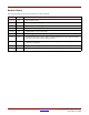
R Example Design Configuration connects to a SPI-4.2 PHY layer device or network processor. Figure 4-1 shows the example design modules architecture and interfaces to the SPI-4.2 core. LoopBack Module SPI-4.
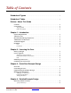
R Chapter 4: Detailed Example Design Demonstration Test Bench The demonstration test bench emulates a PHY device by generating and receiving packet data across the SPI-4.2 interface. The interface between the demonstration test bench and the SPI-4.2 core is illustrated in Figure 4-2. SPI-4.2 Core Demonstration Testbench Data Monitor SrcInFrame Sink Core Sink Static Config Signals RDClk_P RDClk_N RDat_P User Sink Interface SPI-4.
R Demonstration Test Bench • Status Monitor • Testcase Demonstration Testbench Clock Generator Data Monitor SrcInFrame Static Config.
R Chapter 4: Detailed Example Design Startup Module The Startup Module contains three functions: DCM setup, calendar loading, and Dynamic Phase Alignment (DPA) Initialization. These functions are described in detail in the following sections. DCM Startup The DCM Startup is a state machine that ensures that the DCMs are reset in the appropriate order. If they are not reset appropriately, the DCMs will not lock. The Startup Module first asserts DCMReset_TDClk.
R Demonstration Test Bench • RDCLK_RST Holds DCMReset_RDClk for 8 cycles then releases it • RDCLK_LCK Waits for the Locked_RDClk signal. • TSCLK_RST Holds DCMReset_TSClk for 12 cycles then releases it. • TSCLK_LCK Waits for the Locked_TSClk signal. • CLKS_RDY Waits for SnkClksRdy and SrcClksRdy signals. • RELEASE_RST Releases Reset_n. Calendar Loader The second function of the Startup module is the logic to load the calendars.
R Chapter 4: Detailed Example Design Procedures Module The procedures module is a package of functions instantiated in the testcase module to simplify sending data and status to the stimulus module. Using these functions, you can create any desired sequence of data or status. The method by which functions are called varies among languages, and is described in the appendices. The following functions are supported in the procedures module: • send_packet Used to transmit an entire packet of data.
R Demonstration Test Bench Lastly, the signal SnkInFrame is created in the status monitor by inverting SnkOof. This signal is used by the stimulus module to send training. See Appendix C, “Data and Status Monitor Warnings.” Customizing the Demonstration Test Bench The demonstration test bench can be used with default settings or customized to observe the behavior of the SPI-4.2 core for different configurations.
R Table 4-10: Chapter 4: Detailed Example Design Testcase Package User-Defined Constants (Continued) Name MERGE_PAYLOAD Constant Type Integer Default Value (Range) 0 <0 or 1> Description Before data is sent on RDat, the demonstration test bench can either merge an EOP and SOP control word into one payload control word, or it can leave them as two separate control words. 1: Merge EOP and SOP is enabled. 0: Merge EOP and SOP is disabled.
R Demonstration Test Bench Table 4-10: Testcase Package User-Defined Constants (Continued) Constant Type Name Default Value (Range) Description DATA_NUM_TRAIN_SEQ Integer 3 <0 - 255> Sets the number of complete training patterns that the demonstration test bench has to receive on TDat (upon startup) before it stops sending framing sequences on TStat. Once this happens, the demonstration test bench begins sending valid status. TDCLK_PERIOD 2.
R Chapter 4: Detailed Example Design Table 4-11 contains a list of common useful test case signals and descriptions. Table 4-11: Useful Testcase Signals Name Description FullVec An array of bits indicating the last status received on RStat for each channel. For each channel, the corresponding bit is set (1) if the status received was ‘10’ - satisfied, and cleared (0) if the status was ‘01’ - hungry or ‘00’ - starving. NumLinks The number of channels for which the core was configured.
R Demonstration Test Bench and the status for that channel. This sends the status and the channel to the stimulus module for transmission to the core. The stimulus module ensures that the status is sent in the correct location of the calendar sequence. Calendar Sequence Files (Sink and Source) The snk_calendar.dat and src_calendar.dat files are used to define the order that status is sent on the SPI-4.2 Interface.
R 44 Chapter 4: Detailed Example Design www.xilinx.com SPI-4.2 v8.
R Appendix A VHDL Details Procedures Module The procedures module is a package of functions instantiated in the testcase module to simplify the sending of data and status to the Stimulus module. By using these functions, the user can create any desired sequence of data or status. All functions are called from the Testcase module using the following format: Format: (, ) Example: send_packet(ProBusR, 0, 40): A 40-byte long packet is sent on channel 0.
R Appendix A: VHDL Details automatically calculated from the number of bytes sent. ERR has a higher priority than EOP; if EOP and ERR are both ‘1’, the EOPs for the burst is an EOP abort = ‘01’. Table A-2: send_user_data (PBr, SOP, EOP, Err, Addr, bytes) Inputs Name Range Description SOP 0 or 1 Defines if the packet should begin with a SOP. EOP 0 or 1 Defines if the packet should be terminated with an EOP. ERR 0 or 1 Defines if the packet should be terminated with an EOP abort.
R Procedures Module Table A-5: sop_spacing (PBr, Bytes1, Err1, Addr1, EOP2, Err2, Addr2, Bytes2, num_cycles) Inputs (Continued) Name Range Description ADDR2 0 to 255 Channel on which the second packet should be sent. BYTES2 1 to 255 The number of bytes to send in the second burst. NUM_CYCLES 0 to [5 - roundup (BYTES1/2)] The number of idle cycles between the first and second burst. The send_status procedure is used to change the status for a particular channel.
R 48 Appendix A: VHDL Details www.xilinx.com SPI-4.2 v8.
R Appendix B Verilog Details Procedures Module The procedures module is a package of functions instantiated in the Testcase module to simplify sending data and status to the Stimulus module. Use these functions to create any desired sequence of data or status. All functions are called from the Testcase module using the following format: Format: tasks.() Example: tasks.send_packet(0,40): A 40-byte long packet is sent on channel 0.
R Appendix B: Verilog Details The send_user_data procedure is used to transmit a burst of data. The presence of a SOP control word (before the burst of data) and an EOP control word (following the data burst), can be specified. The EOPS (bits 14:13 of the control word following the burst) are automatically calculated from the number of bytes sent. ERR has a higher priority than EOP; if EOP and ERR are both ‘1’, the EOPs for the burst is an EOP abort = ‘01.
R Random Testcase Sample Code Table B-5: sop_spacing (Bytes1, Err1, Addr1, EOP2, Err2, Addr2, Bytes2, num_cycles) Inputs (Continued) Name Range Description ERR2 0 or 1 Defines if the second packet should be terminated with an EOP abort. If set to 0 the EOPs will be calculated from Bytes1. ADDR2 0 to 255 Channel on which the second packet should be sent. BYTES2 1 to 255 The number of bytes to send in the second burst.
R Appendix B: Verilog Details RandIdleRequest = {$random(`RANDOM_SEED + $random(`RANDOM_SEED + $time))} % 100; RandTrainingRequest = {$random(`RANDOM_SEED + $time)} % 100; RandDIP4Request = {$random(`RANDOM_SEED + $time + $random(`RANDOM_SEED))} % 100; RandDIP2Request = {$random($random(`RANDOM_SEED) + $time)} % 100; RandSnkDip2ErrRequest = {$random(`RANDOM_SEED + $random($time))} % 100; //Randomly set TCIdleRequest to 1 if ((RandIdleRequest == 0) || (TCIdleRequest == 1)) begin if (TCIdleRequest == 1) beg
R Random Testcase Sample Code begin if (DIP4RequestCnt > 0) begin DIP4RequestCnt <= DIP4RequestCnt - 1'b1; TCDIP4Request <= 1'b1; end else begin DIP4RequestCnt <= 'b0; TCDIP4Request <= 1'b0; end end else begin TCDIP4Request <= 1'b1; DIP4RequestCnt <= {$random(`RANDOM_SEED + $time)} % 9; end end //Randomly set TCDIP2Request to 1 if ((RandDIP2Request == 0) || (TCDIP2Request == 1)) begin if (TCDIP2Request == 1) begin if (DIP2RequestCnt > 0) begin DIP2RequestCnt <= DIP2RequestCnt - 1'b1; TCDIP2Request <= 1'b1
R Appendix B: Verilog Details begin TCSnkDip2ErrRequest <= 1'b1; SnkDip2ErrRequestCnt <= {$random(`RANDOM_SEED + $time)} % 9; end end //Sends a random sized packet to a random channel if (RandTask == 0) begin tasks.send_packet({$random(`RANDOM_SEED + $time)} % (`NUM_CHANNELS - 1), ($random(`RANDOM_SEED + $time) % 255) + 1'b1); end //Sends a random sized packet to a random channel. Also SOP, EOP, and //Err are randomized else if (RandTask == 1) begin tasks.
R Appendix C Data and Status Monitor Warnings The Data and Status monitors continuously check data sent to and received from the demonstration test bench. There are several common warnings that occur when the Testcase module is modified. The warnings are listed and described below. TDat Warning: Source is segmenting packets This warning means that the Source core is sending payload resumes in the middle of sending a burst. This is acceptable operation if SrcBurstMode = 0.
R 56 Appendix C: Data and Status Monitor Warnings www.xilinx.com SPI-4.2 v8.
R Appendix D Timing Simulation Warning and Error Messages There are several common simulation warnings and error messages when timing simulation is run on the example design. These warnings and messages are described in this appendix. "# TDat Error: Data Mismatch # 4. Expected 000f, Received 000x. 339280 ps" The data mismatch results from the data going to unknown "x" state.
R 58 Appendix D: Timing Simulation Warning and Error Messages www.xilinx.com SPI-4.2 v8.