Introduction Xilinx Blockset Overview Xilinx Blocks System Generator Software Features Xilinx System Generator v2.1 for Using the Xilinx Software Auxiliary Files Simulink User Guide Xilinx Blockset Reference Guide — Printed in U.S.A.
Xilinx System Generator v2.1 Reference Guide About This Manual This document is a reference guide for system designers who are unfamiliar with the System Generator v2.1 and the Xilinx Blockset. Manual Contents This guide covers the following topics: 2 • Chapter 1, Introduction, gives a high-level overview of the System Generator and its uses.
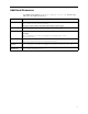
Additional Resources For additional information, go to http://support.xilinx.com. The following table lists some additional resources. Resource Description/URL IP Center Information on Xilinx LogiCOREs and IP solutions. http://www.xilinx.com/ipcenter/ This page contains a link to the Xilinx Xtreme DSP solutions page. Technical Tips Latest news, design tips, and patch information for the Xilinx design environment. http://support.xilinx.com/xlnx/xil_tt_home.
Xilinx System Generator v2.1 Reference Guide Conventions This document uses the following conventions. An example illustrates each convention. Typographical The following conventions are used for all System Generator documents. • Courier font (a fixed-width font) indicates messages, prompts, menu pick items, and dialog box entries that the system displays. speed grade: - 100 • Courier bold indicates literal commands that you enter in a command-line prompt or dialog box.
Contents Chapter 1 Introduction Industry and Product Overview .................................................................................8 System Generator .....................................................................................................9 System Level Modeling with System Generator .......................................................9 The System Generator Design Flow .........................................................................10 Arithmetic Data Types ..............
Xilinx System Generator v2.1 Reference Guide Concat .................................................................................................................30 Constant ..............................................................................................................31 Convert ................................................................................................................31 Counter ..........................................................................................
Gateway Out.........................................................................................................99 Quantization Error Blocks ....................................................................................101 Display .................................................................................................................101 Memory .....................................................................................................................102 Dual Port RAM ............
Xilinx System Generator v2.1 Reference Guide Chapter 1 Introduction This chapter describes the basic concepts and tools of the System Generator v2.1. This chapter contains the following sections.
Introduction constructs for simulation, its synthesizable subset is far too restrictive for system design. System Generator is a software tool for modeling and designing FPGA-based DSP systems in Simulink. The tool presents a high level abstract view of a DSP system, yet nevertheless automatically maps the system to a faithful hardware implementation.
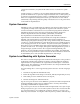
Xilinx System Generator v2.1 Reference Guide 3 and simply use floating point operations in hardware. The answer is that most operations have a sufficiently small dynamic range that a fixed point representation is acceptable, and the hardware realization of fixed point is considerably cheaper. The System Generator Design Flow Simulink provides a graphical environment for creating and modeling dynamical systems.
Introduction The System Generator design flow is shown in the following figure. MATLAB Environment Library (including Xilinx Blockset) Simulink System Model Simulation Input Output + Z –1 k including S-functions Simulation Data Synthesis System Generator Code Generation Software - map to IP libraries - control signals - VHDL design - HDL testbench - constraints - simulation scripts, project files ENTITY mult IS GENERIC(w: PORT(a,b:IN PORT(y:OUT END ENTITY ...
Xilinx System Generator v2.1 Reference Guide Simulink hierarchy into a hierarchical VHDL netlist. In addition, System Generator creates the necessary command files to create the IP block netlists using CORE Generator, invokes CORE Generator, and creates project and script files for HDL simulation, synthesis, technology mapping, placement, routing, and bit stream generation.
Introduction Generator then propagates signal types and precisions as appropriate. The automatically chosen type is the least expensive that preserves full precision. Translations from signed to unsigned and vice versa are automatic as well. System Generator also allows designs to contain elements that cannot be realized in hardware, but assist development and debugging.
Xilinx System Generator v2.1 Reference Guide Bit-True and Cycle-True Modeling System Generator produces a hardware implementation that is bit and cycle true to the system level simulation. We define the term bit and cycle true at the boundaries of the design. The boundaries of a design in System Generator are specified by the presence of Gateway In and Gateway Out blocks.
Xilinx Blockset Overview Chapter 2 Xilinx Blockset Overview This chapter gives an overview of the Xilinx Blockset, including background information on underlying blockset implementation, which will help you understand how each block can be used to create and simulate your designs. This chapter contains the following sections.
Xilinx System Generator v2.1 Reference Guide portion of a Simulink model to be implemented in an FPGA must be built exclusively of Xilinx blocks, with the exception of subsystems denoted as black boxes. Instantiating Xilinx Blocks within a Simulink Model Xilinx blocks can be dragged (from the Simulink library browser, or from an expanded sheet showing the blocks in the library) and dropped onto a Simulink model sheet.
Xilinx Blockset Overview As an example, the figures shown below depict the Xilinx Negate block parameters dialog box with full and user defined precision. Note in the latter case the additional options for selecting quantization and overflow behavior. Figure 2-2: User-Defined Precision Options (available if selected instead of full precision) Valid and Invalid Data In the Xilinx Blockset portion of a Simulink model, every data sample is accompanied by a handshake validation signal.
Xilinx System Generator v2.1 Reference Guide Use of Xilinx Smart-IP Cores by the System Generator To increase hardware performance, most System Generator blocks are implemented using Xilinx Smart-IP (Intellectual Property) LogiCOREs. These are hand crafted modules that make optimal use of FPGA resources to maximize performance. Some System Generator blocks map onto multiple LogiCOREs, for example, the 1024-point FFT, maps onto Dual Port Memory blocks as well as the FFT core itself.
Xilinx Blockset Overview Xilinx LogiCORE Versions The Xilinx LogiCORE blocks (indicating the version numbers being supported by the System Generator) used in Xilinx System Generator v2.1 are listed below. Xilinx Block Xilinx LogiCORE Version Accumulator ACCUMULATOR V5.0 Addressable Shift Register RAM_SHIFT V5.0 Adder/Subtractor ADDSUB V5.0 CIC CIC V1.0 Counter BINARY_COUNTER V5.0 Constant Multiplier MULT_GEN V4.0 Convolutional Encoder CONVOLUTION V1.0 DDS DDS V4.
Xilinx System Generator v2.1 Reference Guide specific parameters are described in the specific block documentation in the next chapter. The remainder of the parameters in each block’s parameters dialog box are common to most blocks. These common parameters are described below. Arithmetic Type In the Type field of the block parameters dialog box, you can choose unsigned or signed (two’s complement) as the datatype of the output signal.
Xilinx Blockset Overview Precision The fundamental computational mode in the Xilinx Blockset is arbitrary precision fixed point arithmetic. Most blocks give you the option of choosing the precision, i.e. the number of bits and binary point position. By default, the output of Xilinx blocks is full precision; that is, sufficient precision to represent the result without error. Most blocks have a User-Defined precision option that fixes the number of total and fractional bits.
Xilinx System Generator v2.1 Reference Guide In the Simulink environment, the Override with Doubles option allows you to simulate the entire design in double precision floating point. This option is useful in selecting fixed point widths or when debugging. If you detect unacceptable quahtization errors with fixed point signals, you can choose to simulate your entire design, or only specific blocks, using double precision floating point signals and arithmetic operations.
Xilinx Blocks Chapter 3 Xilinx Blocks This chapter describes each Xilinx block in detail. Xilinx blocks are grouped within six categories, also shown in the Simulink library browser. They are: • Basic Elements • Communication • DSP • Math • MATLAB I/O • Memory • State Machine Basic Elements The Xilinx Basic Elements library includes the standard building blocks for digital designs.
Xilinx System Generator v2.1 Reference Guide Block Parameters Dialog Box The block parameters dialog box can be invoked by double-clicking the icon in your Simulink model. Figure 3-1: System Generator block parameters dialog box Parameters specific to the System Generator block are: • Xilinx Product Family Supported families currently are: Virtex, Virtex2, Spartan2, and VirtexE. • Target Directory Specify where the output files (VHDL, cores, and project files) will be written.
Xilinx Blocks The wrapper file is named to match the top level VHDL file generated for your project. For example, if your top level file is named design_project, the wrapper is called design_project_testbench.vhd. The top level of the project is taken to be the Simulink sheet from which you invoked the System Generator token. In addition to the testbench VHDL file, test vectors (.dat files) are also generated. These vectors represent the inputs and expected outputs seen in Simulink simulation.
Xilinx System Generator v2.1 Reference Guide Addressable Shift Register The Xilinx Addressable Shift Register block is a variable-length shift register (or delay chain). This block differs from the Xilinx Delay block in that the amount of latency experienced by data from input to block output is variable and depends on the address value. Data presented to the block will traverse the entire delay chain. The output of the block is not necessarily the output of the last register in the chain, however.
Xilinx Blocks Block Parameters Dialog Box The Addressable Shift Register Block Parameters Dialog Box can be invoked by double-clicking the icon in your Simulink model.
Xilinx System Generator v2.1 Reference Guide Black Box The Xilinx Black Box token enables you to instantiate your own specialized functions in your model, and subsequently into a generated design. Like the System Generator token, the Black Box token can be placed in any Simulink subsystem, identifying the subsystem as a black box. If you choose to include functionality in your Simulink model that does not exist in the current blockset, any Simulink subsystem can be treated as a black box.
Xilinx Blocks infer them in the generated VHDL. The block parameters dialog box can be invoked by double-clicking the icon in your Simulink model. Figure 3-3: Black Box block parameters dialog box Parameters specified as cell arrays (generic or parameter names, types, and values) permit several methods for entering data. You can specify your data directly in the dialog box as shown. You may also specify the cell arrays as MATLAB expressions. This is useful if you have many elements in your cell arrays.
Xilinx System Generator v2.1 Reference Guide input and output ports respectively. To configure the black box, enter the parameters in the black box block parameters dialog box as shown in the figure below. Figure 3-4: Customizing Clocks in the Black Box block parameters dialog box These settings indicate that the black box should have clocks named fast_clk and slow_clk.
Xilinx Blocks Constant The Xilinx Constant block generates a constant. This block is similar to the Simulink constant block, but can be used to drive the inputs on Xilinx blocks. Block Parameters Dialog Box The block parameters dialog box can be invoked by double-clicking the icon in your Simulink model. Figure 3-6: Constant block parameters dialog box Parameters specific to the block are: • Constant Value: specifies the value of the constant.
Xilinx System Generator v2.1 Reference Guide Block Parameters Dialog Box The block parameters dialog box can be invoked by double-clicking the icon in your Simulink model. Figure 3-7: Convert block parameters dialog box All the parameters of the Convert block are parameters common to other blocks. Please refer to the Common Parameters section in the previous chapter for details.
Xilinx Blocks The block can be configured as a free running up or down counter by selecting the Provide Reset Pin option on the block parameters dialog box. In this case, the block has a reset input port in addition to its output port. The output for a free running up counter is calculated as follows: Here N denotes the number of bits in the counter. The down counter calculations replace addition by subtraction.
Xilinx System Generator v2.1 Reference Guide Block Parameters Dialog Box The Counter block parameters dialog box is invoked by double-clicking the block icon. Figure 3-8: Counter block parameters dialog box Parameters specific to the block are: • Number of Bits: specifies the number of bits in the counter. • Binary Point Position: specifies the location of the binary point. • Arithmetic Type: specifies the block ouput to be either Signed or Unsigned.
Xilinx Blocks Xilinx LogiCORE The block always uses the Xilinx LogiCORE: Binary Counter V5.0. The Core datasheet can be found on your local disk at: %XILINX%\coregen\ip\xilinx\eip1\com\xilinx\ip\baseblox_v5_0\do c\binary_counter.pdf Delay The Xilinx Delay block is a delay line (also called a shift register) of configurable length, allowing you to add latency to your design. Data presented at the input will appear at the output after a user specified number of sample periods.
Xilinx System Generator v2.1 Reference Guide Down Sample The Xilinx Down Sample block reduces the sample rate at the point where the block is placed in your design. The input signal is undersampled so that every nth input sample is presented at the output and held. Output sample period is ki, where k is the sampling rate and i is the input sample period. In Simulink, a block changes its output right after it is enabled. In hardware, a register does not change until the clock enable is sampled, i.e.
Xilinx Blocks Block Parameters Dialog Box The block parameters dialog box can be invoked by double-clicking the icon in your Simulink model. Figure 3-12: Down sample block parameters dialog box Parameters specific to the block are: • Sampling Rate: must be an integer greater or equal to 2. This is the ratio of the output sample period to the input, and is essentially a sample rate divider. For example, a ratio of 2 indicates a 2:1 division of the input sample rate.
Xilinx System Generator v2.1 Reference Guide Mux The Xilinx Mux block implements a multiplexer. The block has one select input (type unsigned) and a userconfigurable number of data bus inputs, ranging from 2 to 32. Block Parameters Dialog Box The block parameters dialog box can be invoked by double-clicking the icon in your Simulink model. Figure 3-13: Mux block parameters dialog box Parameters specific to the block are: • Number of Inputs: specifies the number of data bus inputs, from 2 to 32.
Xilinx Blocks %XILINX%\coregen\ip\xilinx\eip1\com\xilinx\ip\baseblox_v5_0\do c\bus_mux.pdf Parallel to Serial The Parallel to Serial block takes an input word and splits it into N time multiplexed output words where N equals the number of input bits/ number of output bits. The order of the output is either least significant bit first or most significant bit first.
Xilinx System Generator v2.1 Reference Guide Block Parameters Dialog Box Figure 3-15: Parallel to Serial block parameters dialog box Parameters specific to the block are: • Output Order: Most significant word first or least significant word first. Word size is determined by the size of the input port. • Output Arithmetic Type: unsigned or signed • Number of Input Bits: Input width. Must match size of input port. • Number of Output Bits: Output width. Must divide Number of Input Bits evenly.
Xilinx Blocks Block Interface The block has one input port for the data and an optional input reset port. The initial output value is specified by the user in the block parameters dialog box (below). Data presented at the input will appear at the output after one sample period. Upon reset, the register assumes the initial value specified in the parameters dialog box. The Register block differs from the Xilinx Delay block by providing an optional reset port and a user specifiable initial value.
Xilinx System Generator v2.1 Reference Guide Reinterpret The Reinterpret block forces its output to a new type without any regard for retaining the numerical value represented by the input. The binary representation is passed through unchanged, so in hardware this block consumes no resources. The number of bits in the output will always be the same as the number of bits in the input.
Xilinx Blocks Block Parameters Dialog box Figure 3-17: Reinterpret block parameters dialog box Parameters specific to the block are: • Force Arithmetic Type: When checked, the Output Arithmetic Type parameter can be set and the output type will be forced to the arithmetic type chosen according to the setting of the Output Arithmetic Type parameter. When unchecked, the arithmetic type of the output will be unchanged from the arithmetic type of the input.
Xilinx System Generator v2.1 Reference Guide The following waveform illustrates the block’s behavior: Figure 3-18: Example of Serial to Parallel behavior This example illustrates the case where the input width is 1, output width is 4, word size is 1 bit, and the block is configured for most significant word first. Block Interface The Serial to Parallel block has one input and one output port. The input port can be any size. The output port size is indicated on the block parameters dialog box.
Xilinx Blocks • Binary Point: Output binary point location Other parameters used by this block are explained in the Common Parameters section of the previous chapter. The Parallel to Serial block does not use a Xilinx LogiCORE. An error is reported when the number of output bits cannot be divided evenly by the number of input bits. The minimum latency for this block is zero. Set Valid Bit The Xilinx Set Valid Bit block flags input data as invalid when the signal on the valid bit input port is zero.
Xilinx System Generator v2.1 Reference Guide only the first three fractional bits. The following diagram illustrates how to extract all but the top 16 and bottom 8 bits of the input. Figure 3-21: Slice block operation Block Parameters Dialog Box The block parameters dialog box can be invoked by double-clicking the icon in your Simulink model.
Xilinx Blocks Figure 3-22: Slice block parameters dialog box showing different options Parameters specific to the block are: • Specify Range As: (Two Bit Locations | Upper Bit Location + Width |Lower Bit Location + Width). Allows the user to specify either the bit locations of both end-points of the slice or one end-point along with number of bits to be taken in the slice. • Width of Slice (Number of Bits): specifies the number of bits to extract.
Xilinx System Generator v2.1 Reference Guide The following diagram illustrates the operation of this block. Figure 3-23: Sync block use This diagram shows a two-channel Xilinx Sync Block connected to two signal sources, with one producing a sawtooth wave and the other a sine wave. The sawtooth generator is able to produce its output much more quickly than the sine generator.
Xilinx Blocks It is instructive to note that the following model produces behavior identical to the one with the Sync block. This one, though, requires the designer to examine the two upstream pipelined sources and to insert the correct delay line length to balance the two pipelines. Moreover, should a pipeline stage be either added to or removed from the sine wave generator, the pipeline balancing delay line would have to be re-tuned. The Xilinx Sync block allows such balancing operations to be automated.
Xilinx System Generator v2.1 Reference Guide added to the channel that is last to present a valid input sample. Note that if this parameter is zero, the block has a feed-through path; otherwise, it does not. Other parameters used by this block are described in the Common Parameters section of a previous chapter in this manual. The Xilinx Sync block does not use a Xilinx LogiCORE. Up Sample The Xilinx Up Sample block increases the sample rate at the point where the block is placed in your design.
Xilinx Blocks from din to dout. Whenever possible, put a register or delay block after an up sample block. Figure 3-28: Example of up sample block behavior with zero padding Block Parameters Dialog Box The block parameters dialog box can be invoked by double-clicking the icon in your Simulink model. Figure 3-29: Up Sample block parameters dialog box Parameters specific to the block are: • Sampling Rate: must be an integer with a value of 2 or greater.
Xilinx System Generator v2.1 Reference Guide Communication The blocks in the Communication library implement functions used in digital communications systems, including convolutional and block channel coding, interleaving, and utility functions. Convolutional Encoder The Xilinx Convolutional Encoder block implements an encoder for convolutional codes.
Xilinx Blocks Block Parameters Dialog Box The following figure shows the block parameters dialog box. Figure 3-31: Convolutional encoder block parameters dialog box Parameters specific to the block are: • Output Rate: 2 or 3. Number of output bits generated per input bit. A rate 1/2 encoder will have an output rate of 2. • Convolution Code 1: Used to generate least significant bit of the output. Length of convolution code must be between 3 and 9 (inclusive).
Xilinx System Generator v2.1 Reference Guide Depuncture The Xilinx Depuncture block allows you to insert arbitrary symbol into your input data at the location specified by the depuncture code and creates a new value. This value is presented as output from the block.
Xilinx Blocks Block Parameters Dialog Box The Xilinx depuncture block can be configured using its Block Parameters dialog box. Figure 3-33: Depuncture block parameters dialog box Parameters specific to the Xilinx Puncture block are: • Depuncture Code: specifies the depuncture pattern for inserting the string to the input. • Insert Symbol: specifies the binary word to be inserted in the depuncture code.
Xilinx System Generator v2.1 Reference Guide Figure 3-34: Forney convolutional interleaver with a constant difference between consecutive branches When the block is in deinterleaver mode, the input data sampled on the DIN port is multiplexed into and out of B shift registers onto the DOUT port using two (synchronized) commutator arms. Branch 0 will have a shift register of length (B-1)*L. Branch (B-1) shall have a shift register length of zero.
Xilinx Blocks When the branch lengths are specified as an array, the block operates the same in either interleaver or deinterleaver mode because the array fully defines the length of all the branches. The array must have length B, matching the number of branches. The reset pin (rst) will set the commutator arms to branch 0, but will not clear the branches of data. Block Interface The Interleaver/Deinterleaver block has two input and one output ports.
Xilinx System Generator v2.1 Reference Guide The Core datasheet can be found on your local disk at: %XILINX%\coregen\ip\xilinx\eip1\com\xilinx\ip\sid_v1_1\doc\sid .pdf This is a licensed core, available for purchase on the Xilinx web site at: http://www.xilinx.com/ipcenter/interleaver Puncture The Xilinx Puncture block allows you to remove arbitrary bits specified as a puncture code from your input data and create a new value. This value is presented as the output from the block.
Xilinx Blocks Block Parameters Dialog Box The Xilinx puncture block can be configured using its Block Parameters dialog box. Figure 3-38: Puncture block parameters dialog box Parameters specific to the Xilinx Puncture block are: • Puncture Code: specifies the puncture pattern for removing the bits from the input. Other parameters used by this block are described in the Common Parameters section of the previous chapter. The Puncture block does not use a Xilinx LogiCORE.
Xilinx System Generator v2.1 Reference Guide The probability of each of the three outcomes depends on the particular ReedSolomon code and the nature of the communications channel. The Simulink blocksets provide excellent capabilities for modeling communication channels and ascertaining these probabilities. Block Interface The Xilinx RS Decoder Block has two input (din, rst) and four output (dout, info, fail, err_cnt) ports.
Xilinx Blocks Block Parameters Dialog Box The RS Decoder block can be configured using its Block Parameters dialog box. Figure 3-40: Reed-Solomon Decoder block parameters dialog box Parameters specific to the RS Decoder block are: • Communication Code Specification: specifies the type of RS Decoder desired. The choices are: ♦ Custom: allows you to set all the block parameters. ♦ ATSC: implements ATSC (Advanced Television Systems Committee) standard (207, 187) shortened RS code.
Xilinx System Generator v2.1 Reference Guide ♦ IESS-308 (208): implements IESS-308 specification (208, 192) shortened RS code. ♦ IESS-308 (219): implements IESS-308 specification (219, 201) shortened RS code. ♦ IESS-308 (225): implements IESS-308 specification (225, 205) shortened RS code. • Symbol Width: specifies the symbol width for the RS code. The RS decoder supports symbol width from 3 to 12. • n: specifies the length of the RS code.
Xilinx Blocks • Scaling Factor: Scaling factor for the generator polynomial root index. Normally h is 1; however, it can be any positive integer between 1 and (216-1). • Provide Start Pin: when checked, the block has optional start input pin. • Enable Erasure Decoding: when checked, the block has optional pins erase at the input and erase_cnt at the output. Other parameters used by this block are described in the Common Parameters section of the previous chapter.
Xilinx System Generator v2.1 Reference Guide type of errors that can be corrected depends on the characteristics of the ReedSolomon code. Reed-Solomon codes are a subset of BCH (Bose, Chaudhuri, and Hocquenghem) codes and are linear block codes. A Reed-Solomon code is specified as RS(n,k) with sbit symbols. Reed-Solomon codes are usually referred to as (n,k) codes, where n is the total number of symbols in a code block and k is the number of information or data symbols.
Xilinx Blocks Block Interface The Xilinx RS Encoder block has two inputs (din, rst) and three output (dout, info and rfd) ports. The RS Encoder block also has optional start and bypass input ports. Figure 3-43: Reed-Solomon Encoder icons, including optional ports The port descriptions are: Communication • din: carries the input information symbols of the RS code. The din signal must be an UFixS_0 where S is equal to the symbol width (3 to 12). • rst: carries the reset signal for the RS encoder.
Xilinx System Generator v2.1 Reference Guide Block Parameters Dialog Box The RS Encoder block can be configured using its Block Parameters dialog box. Figure 3-44: Reed-Solomon Encoder block parameters dialog box Parameters specific to the RS Encoder block are: • Code Specification: specifies the type of RS Encoder desired. The choices are: ♦ ♦ ♦ ♦ ♦ ♦ ♦ ♦ 66 Custom: allows you to set all the block parameters.
Xilinx Blocks ♦ IESS-308 (225): implements IESS-308 specification (225, 205) shortened RS code. • Symbol Width: specifies the symbol width for the RS code. The RS encoder supports symbol width from 3 to 12. • n: specifies the length of the RS code. The RS encoder supports code with length from (2sw - 1) to 3, where sw is symbol width. • k: specifies the number of information symbols in a RS code. The RS encoder supports code with length from (n-2) to max((n-256), 1).
Xilinx System Generator v2.1 Reference Guide Other parameters used by this block are described in the Common Parameters section of the previous chapter. The RS Encoder block cannot be placed in an enabled subsystem in System Generator v2.1. See the Enabled Subsystems section (within the MATLAB I/O library documentation) explanation for more details. Latency The RS Encoder has a 6 sample period latency for CCSDS code specification and a 4 sample period latency for all other specifications.
Xilinx Blocks Constraint length Optimal convolution codes for decoding 1/2 rate encoders Optimal convolution codes for decoding 1/3 rate encoders 9 111101101, 110011011 111101101, 110011011, 100100111 Block Interface The Viterbi Decoder has either two or three input ports and one output port. The decoder can have either two or three input ports depending on the configurable parameter indicating encoder output rate. Use of hard coding requires input data to be 1 bit wide.
Xilinx System Generator v2.1 Reference Guide • Traceback Length: Length of the traceback through the Viterbi trellis. Optimal length is considered to be between 5 and 7 times the constraint length. • Convolution Code 1: Used to decode data on input port din1. Length of convolution code must be between 3 and 9 (inclusive). • Convolution Code 2: Used to decode data on input port din2. Length of convolution code must be between 3 and 9 (inclusive).
Xilinx Blocks Block Interface The CIC Block has one input and one output port. The input port can be between 1 and 32 bits (inclusive). The two basic building blocks of a CIC filter are the integrator and the comb. A single integrator is a single-pole IIR filter with a transfer function of: H(z) = (1 – z-1)-1 The integrator’s unity feedback coefficient is y[n] = y[n-1] + x[n].
Xilinx System Generator v2.1 Reference Guide Block Parameters Dialog Box The CIC Block can be configured using its Block Parameters dialog box: Figure 3-47: CIC block parameters dialog box Parameters specific to this block are: • Filter Type: Interpolator or Decimator • Number of Stages: 1 to 8 (inclusive) • Sample Rate Change: 8 to 16384 (inclusive) • Differential Delay: 1 or 2 Other parameters used by this block are described in the Common Parameters section of the previous chapter.
Xilinx Blocks DDS The Xilinx DDS Block implements a direct digital synthesizer (DDS), also commonly called a numerically controlled oscillator (NCO). The block employs a look-up table scheme to generate real or complex valued sinusoids. An internal look-up table stores samples representing one period of a sinusoid. A digital integrator (accumulator) is then used to generate a suitable phase argument that is mapped by the look-up table into the desired output waveform.
Xilinx System Generator v2.1 Reference Guide Block Parameters Dialog Box The block parameters dialog box can be invoked by double-clicking the icon in your Simulink model. Figure 3-49: DDS block parameters dialog box Parameters specific to the DDS block are: 74 • Function: specifies the block output to be sine, cosine, or both. • Negative Sine: when checked, the sine output is negated. • Negative Cosine: when checked, the cosine output is negated.
Xilinx Blocks • Phase Increment Type: specifies ∆θ to be either constant or register. Choice of register activates optional ports on the block. • Phase Increment: specifies value of phase increment constant, a multiple of 2π. The number of bits is determined in one of two ways. If the increment type is Register, the number of bits is set to the width of the data port. If the increment type is Constant, the number of bits is inferred from the phase increment value.
Xilinx System Generator v2.1 Reference Guide for k=0, 1, ... , N-1, where WN = e 2π ( – i ) -----N is a principal N-th root of unity. The FFT block accepts as input a stream of complex data represented as a pair of Xilinx fixed point data and computes successive DFTs of nonoverlapping frames of N data samples.
Xilinx Blocks • Memory Usage: number of memory banks used to compute the transform, one of Single, Double, Triple (not used for 16 point FFTs). • Scale Output By: one of 1/N or 1/(2N). • Overflow characteristic: block behavior when internal overflow occurs; you may choose to invalidate the output (if checkbox is selected) or to stop the simulation in the event of an overflow (if checkbox is not selected).
Xilinx System Generator v2.
Xilinx Blocks The Dual Port Block Memory LogiCORE datasheet can be found on your local disk at: %XILINX%\coregen\ip\xilinx\eip1\com\xilinx\ip\blkmemdp_v3_2\do c\dp_block_mem.pdf FIR The Xilinx FIR Filter Block implements a finite-impulse response (FIR) digital filter, or a bank of identical FIR filters (multichannel mode). An N-tap filter is defined by N filter coefficients (or taps) h(0), h(1), ....,h(n1). Here each h(i) is a Xilinx fixed point number.
Xilinx System Generator v2.1 Reference Guide Block Parameters Dialog Box The block parameters dialog box can be invoked by double-clicking the icon in your Simulink model. Figure 3-53: FIR block parameters dialog box Parameters specific to the block are: 80 • Coefficients: vector of filter coefficients; note that these can be evaluated from a MATLAB workspace variable and may in turn be computed by MATLAB. You can also refer to examples in the System Generator Tutorial.
Xilinx Blocks • Polyphase behavior: Decimation, Interpolation, Single rate. • Latency: specify input sample period latency. • Hardware Over-Sampling Rate: Hardware clocks per sample. This affects hardware implementation only, and has no effect on simulation. In multi-channel mode, this factor will multiply the implicit oversampling factor. Other parameters used by this block are explained in the Common Parameters section of the previous chapter.
Xilinx System Generator v2.1 Reference Guide Block Parameters Dialog Box The block parameters dialog box can be invoked by double-clicking the icon in your Simulink model. Figure 3-54: Accumulator block parameters dialog box Parameters specific to the block are: • Number of Bits (output width): specifies the output width which must match the input width. If the data input does not match the output width, an error is reported.
Xilinx Blocks %XILINX%\coregen\ip\xilinx\eip1\com\xilinx\ip\baseblox_v5_0\do c\accum.pdf AddSub The Xilinx AddSub block implements an adder/subtractor. The operation can be fixed (Add or Subtract) or changed dynamically under control of the sub mode signal. Block Parameters Dialog Box The block parameters dialog box can be invoked by double-clicking the icon in your Simulink model.
Xilinx System Generator v2.1 Reference Guide uses the Xilinx LogiCORE Adder Subtractor V5.0. Otherwise, the block is implemented as a synthesizable VHDL module. The Core datasheet can be found on your local disk at: %XILINX%\coregen\ip\xilinx\eip1\com\xilinx\ip\baseblox_v5_0\do c\addsub.pdf CMult The Xilinx CMult block implements a gain operator, with output equal to the product of its input by a constant value. This value can be a MATLAB expression that evaluates to a constant.
Xilinx Blocks saturated as needed. A positive value is implemented as an unsigned number, a negative value as signed. • Number of Bits in Constant: specifies the bit location of the binary point of the constant, where bit zero is the least significant bit. • Multiplier Type: specifies the implementation to be parallel or sequential. • Memory Type: specifies whether to use distributed RAM or block RAM.
Xilinx System Generator v2.1 Reference Guide Block Parameters Dialog Box The block parameters dialog box can be invoked by double-clicking the icon in your Simulink model. Figure 3-57: Inverter block parameters dialog box Parameters used by this block are explained in the Common Parameters section of the previous chapter of the Reference Guide. Xilinx LogiCORE The Inverter block uses the Xilinx LogiCORE Bus Gate V5.
Xilinx Blocks Block Parameters Dialog Box The block parameters dialog box can be invoked by double-clicking the icon in your Simulink model. Figure 3-58: Logical block parameters dialog box Parameters specific to the block are: • Logical Function: specifies one of the following bitwise logical operators: AND, NAND, OR, NOR, XOR, XNOR. • Number of Inputs: specifies the number of inputs: either 2, 3, or 4. • Align Binary point: specifies that the block must align binary points automatically.
Xilinx System Generator v2.1 Reference Guide Mult The Xilinx Mult block implements a multiplier. It computes the product of the data on its two input ports, producing the result on its output port. The block supports a size-performance tradeoff in its implementation. It can be implemented either as a parallel multiplier that operates on the full width data (faster and larger), or as a sequential multiplier that computes the result from smaller partial products (slower and smaller).
Xilinx Blocks Figure 3-60: Mult block parameters dialog box - sequential type Parameters specific to the Mult block are: • Multiplier Type: directs the implementation to be either parallel or sequential. • Require Maximum Pipelining: directs the core to be pipelined to the fullest extent possible. • Use Dedicated High-Speed Multipliers: when checked, directs the core to use embedded multipliers (available in Virtex-II only, and when the multiplier type is parallel).
Xilinx System Generator v2.1 Reference Guide Negate The Xilinx Negate block computes the arithmetic negation (two’s complement) of its input. The block can be implemented either as a Xilinx LogiCORE or as a synthesizable VHDL module. Block Parameters Dialog Box The block parameters dialog box can be invoked by double-clicking the icon in your Simulink model.
Xilinx Blocks ♦ equal-to (a = b) ♦ not-equal-to (a != b) ♦ less-than (a < b) ♦ greater-than (a > b) ♦ less-than-or-equal-to (a <= b) ♦ greater-than-or-equal-to (a >= b) The output of the block is a 1-bit unsigned number. It is 1 if the comparison is true and 0 if false. Block Parameters Dialog Box The block parameters dialog box can be invoked by double-clicking the icon in your Simulink model.
Xilinx System Generator v2.1 Reference Guide Scale The Xilinx Scale block scales its input by a power of two. The power can be either positive or negative. The block has one input and one output. The scale operation has the effect of moving the binary point without changing the bits in the container. Block Parameters Dialog Box The block parameters dialog box can be invoked by double-clicking the icon in your Simulink model.
Xilinx Blocks Block Parameters Dialog Box The block parameters dialog box can be invoked by double-clicking the icon in your Simulink model. Figure 3-64: Shift block parameters dialog box Parameters specific to the Shift block are: • Shift Direction: specifies a direction, Left or Right. The Right shift moves the input toward the least significant bit within its container, with appropriate sign extension. Bits shifted out of the container are discarded.
Xilinx System Generator v2.1 Reference Guide fundamental sinusoid lie in the half-open interval [-1, 1]. If you need a balanced representation, one can be built using the Single Port RAM block with the appropriate initialization vector. Block Parameters Dialog Box The block parameters dialog box can be invoked by double-clicking the icon in your Simulink model.
Xilinx Blocks 64. This corresponds to one CLB per output bit. If the table depth is greater than 64, a quarter wave is stored, and additional logic is used to generate the remaining portions of the wave. Storing only the quarter wave for the large tables reduces the area needed. Block memory stores a full wave for all table depths and widths that can be implemented in a single block memory. Otherwise, values are stored as a quarter wave.
Xilinx System Generator v2.1 Reference Guide Block Parameters Dialog Box The block parameters dialog box can be invoked by double-clicking the icon in your Simulink model. Figure 3-66: Threshold block parameters dialog box The block parameters do not control the output data type because the output is always a signed fixed point integer that is 2 bits long. All the parameters used by this block are explained in the Common Parameters section of the previous chapter.
Xilinx Blocks LogiCOREs, as well as signals and control circuits to drive the clock network. Consequently, most System Generator blocks do not provide an explicit enable port. There are two exceptions> the Register block and the Addressable Shift Register block, which fundamentally require a CE port in order to target a high performance hardware implementation. Simulink Enabled Subsystems can be used to enable blocks and subsystems.
Xilinx System Generator v2.1 Reference Guide The block parameters dialog box can be invoked by double-clicking the icon in your Simulink model. Figure 3-68: Gateway In block parameters dialog box Parameters specific to the Gateway In block are: • IOB Timing Constraint: In hardware, a Gateway In is realized as a set of input/output buffers (IOBs). There are three ways to constrain the timing on IOBs. They are None, Data Rate, and Data Rate, Set 'FAST' Attribute.
Xilinx Blocks It should be noted there is a valid bit that accompanies the data signal. It is constrained at the same rate. For more information concerning the valid bit, refer to the Hardware Handshaking section in Chapter 1 of this manual. If Data Rate, Set 'FAST' Attribute is selected, the OFFSET = IN constraints described above are produced. In addition, a FAST slew rate attribute is generated for each IOB. This reduces delay but increases noise and power consumption.
Xilinx System Generator v2.1 Reference Guide The block parameters dialog box can be invoked by double-clicking the icon in your Simulink model. Figure 3-69: Gateway Out block parameters dialog box Parameters specific to the Gateway Out block are: • IOB Timing Constraint: In hardware, a Gateway Out is realized as a set of input/output buffers (IOBs). There are three ways to constrain the timing on IOBs. They are None, Data Rate, and Data Rate, Set 'FAST' Attribute.
Xilinx Blocks NET "Dout<2>" FAST; NET "Dout_valid" FAST; • Specify IOB Location Constraints: Checking this option allows IOB location constraints to be specified. • IOB Pad Locations, e.g. {'Valid Bit', 'MSB', ...., 'LSB'}: IOB pin locations can be specified as a cell array of strings in this edit box. The locations are package-specific.
Xilinx System Generator v2.1 Reference Guide Memory This section contains Xilinx blocks that use Xilinx memory LogiCOREs. Dual Port RAM The Xilinx Dual Port RAM block implements a random access memory (RAM). Block Interface The block has two independent sets of ports for simultaneous reading and writing. Each port set has one output port and three input ports for address, input data, and write enable (WE).
Xilinx Blocks by the port’s address input. During a write cycle, the user can configure the behavior of the data out ports A/B to one of the following choices: • Read After Write • Read Before Write • No Read On Write The write modes can be described with the help of the figure below. In the figure, the memory has been set to an initial value of 5 and the address bit is specified as 4.
Xilinx System Generator v2.1 Reference Guide Virtex, Virtex-E and Spartan-II families support only Read After Write. Virtex-II supports all modes. Block Parameters Dialog Box The block parameters dialog box can be invoked by double-clicking the icon in your Simulink model. Figure 3-71: Dual Port RAM block parameters dialog box Parameters specific to the block are: • Depth: specifies the number of words in the memory for Port A, which must be a positive integer.
Xilinx Blocks Xilinx LogiCORE The block uses the Xilinx LogiCORE: Dual Port Block Memory v3.2 The address width must be equal to log 2d where d denotes the memory depth. The tables below show the widths that are acceptable for each depth.
Xilinx System Generator v2.1 Reference Guide FIFO The Xilinx FIFO block implements a First-In-First-Out memory queue. Values presented at the module’s data-input port is written to the next available empty memory location when the write-enable input is one. The memory full status output port is assserted to one when no unused locations remain in the module’s internal memory. The percent full output port indicates the percentage of internal memory in use, represented with user-specified precision.
Xilinx Blocks • Store Only Valid Data: when checked, the block will not store any invalid data words; i.e., when the din sample is invalid, the WE (write enable) input is disregarded (if 1) and the sample is not written into the FIFO. • Zero Initial Output: when checked, initial output from the block is 0. Otherwise, it is NaN (not a number). • Memory Type: specifies the implementation that must be used either for distributed or block RAM.
Xilinx System Generator v2.1 Reference Guide Block Parameters Dialog Box The block parameters dialog box can be invoked by double-clicking the icon in your Simulink model. Figure 3-73: ROM block parameters dialog box Parameters specific to this block are: 108 • Depth: specifies the number of words stored; must be a positive integer. • Initial Value Vector: specifies the initial value. When the vector is longer than the ROM depth, the vector’s trailing elements are discarded.
Xilinx Blocks Other parameters used by this block are explained in the Common Parameters section of the previous chapter. Xilinx LogiCORE The block always uses a Xilinx LogiCORE: Single Port Block Memory V3.2 or Distributed Memory V5.0. For the block memory, the address width must be equal to log 2d where d denotes the memory depth. The tables below indicate the widths that are acceptable for each depth.
Xilinx System Generator v2.1 Reference Guide between 16 to 4096, inclusive for the other FPGA families. The word width must be between 1 and 1024, inclusive. The Core datasheet for the Single Port Block Memory may be found locally at: %XILINX%\coregen\ip\xilinx\eip1\com\xilinx\ip\blkmemsp_v3_2\do c\sp_block_mem.pdf The Core datasheet for the Distributed Memory may be found on your local disk at: %XILINX%\coregen\ip\xilinx\eip1\com\xilinx\ip\c_dist_mem_v5_0\ doc\dist_mem.
Xilinx Blocks Block Parameters Dialog Box The block parameters dialog box can be invoked by double-clicking the icon in your Simulink model. Figure 3-74: Single Port RAM block parameters dialog box Parameters specific to this block are: • Depth: specifies the number of words stored; must be a positive integer. • Initial Value Vector: specifies the initial value. When the vector is longer than the RAM, the vector’s trailing elements are discarded.
Xilinx System Generator v2.1 Reference Guide • Read After Write • Read Before Write • No Read On Write The write modes can be described with the help of the figure shown below. In the figure the memory has been set to an initial value of 5 and the address bit is specified as 4. When using No Read On Write mode, the output is unaffected by the address line and the output is the same as the last output when the WE was 0.
Xilinx Blocks Xilinx LogiCORE The block always uses a Xilinx LogiCORE Single Port Block Memory V3.2 or Distributed Memory V5.0. For the block memory, the address width must be equal to log 2d where d denotes the memory depth. The tables below show the width that is acceptable for each depth.
Xilinx System Generator v2.1 Reference Guide %XILINX%\coregen\ip\xilinx\eip1\com\xilinx\ip\blkmemsp_v3_2\do c\sp_block_mem.pdf The Core datasheet for the Distributed Memory can be found on your local disk at: %XILINX%\coregen\ip\xilinx\eip1\com\xilinx\ip\c_dist_mem_v5_0\ doc\dist_mem.pdf State Machine The State Machine library provides a method for implementing Mealy and Moore state machines.
Xilinx Blocks stream of bits. The state transition diagram and equivalent transition table are shown below. Figure 3-77: Mealy State Machine example transition diagram and table The table lists the next state and output that result from the current state and input. For instance, if the current state is 3 and the input is 1, the next state is 1 and the output is 1, indicating the detection of the desired sequence.
Xilinx System Generator v2.1 Reference Guide The rows of the matrices correspond to the current state, and columns correspond to the input value. The next state logic and state register in this block are implemented with high speed dedicated block RAM. The output logic is implemented using a distributed RAM configured as a lookup table, and therefore has zero latency. Block Parameters Dialog Box The block parameters dialog box can be invoked by double-clicking the icon in your Simulink model.
Xilinx Blocks A block diagram of this type of state machine is shown below: Figure 3-80: Moore State Machine block diagram The block is configured by providing a next state matrix and an output array. They are defined by the state machine’s next state/output table. For example, consider the problem of designing a state machine to recognize the pattern ’1011’ within a serial stream of bits. The state transition diagram and equivalent transition table are shown below.
Xilinx System Generator v2.1 Reference Guide The Next State Matrix and the and Output Array are composed in the following way: Figure 3-82: Construction of Next State and Output matrices The rows of the matrices correspond to the current state. The next state matrix has one column for each input value. The output array has only one column, as the input value does not affect the output of the state machine.
Xilinx Blocks Xilinx LogiCORE This block uses Version 3.2 of the Xilinx Single Port Block Memory LogiCORE and Version 5.0 of the Xilinx Distributed RAM LogiCORE. The Core datasheet for the Single Port Block Memory may be found locally at: %XILINX%\coregen\ip\xilinx\eip1\com\xilinx\ip\blkmemsp_v3_2\do c\sp_block_mem.pdf The Core datasheet for the Distributed Memory may be found on your local disk at: %XILINX%\coregen\ip\xilinx\eip1\com\xilinx\ip\c_dist_mem_v5_0\ doc\dist_mem.
Xilinx System Generator v2.1 Reference Guide stream of bits. The state transition diagram and equivalent transition table are shown below. Figure 3-85: Registered Mealy State Machine example transition diagram and table The table lists the next state and output that result from the current state and input. For instance, if the current state is 3 and the input is 1, the next state is 1 and the output is 1, indicating the detection of the desired sequence.
Xilinx Blocks The Registered Mealy State Machine block is configured with next state and output matrices obtained from the next state/output table discussed above. These matrices are constructed as follows: Figure 3-86: Construction of Next State and Output matrices The rows of the matrices correspond to the current state, and columns correspond to the input value. Block Parameters Dialog Box The block parameters dialog box can be invoked by double-clicking the icon in your Simulink model.
Xilinx System Generator v2.
Xilinx Blocks Registered Moore State Machine The Xilinx Registered Moore State Machine block implements a state machine whose output depends only on the current state. This block is like the Moore State Machine block, except that its output logic is registered. A block diagram of this type of state machine is shown below: Figure 3-88: Registered Moore State Machine block diagram The block is configured by providing a next state matrix and an output array.
Xilinx System Generator v2.1 Reference Guide stream of bits. The state transition diagram and next state/output table are shown below. Figure 3-89: Registered Moore State Machine example transition diagram and table The table lists the next state and output that result from the current state and input. For example, if the current state is 4, the output is 1 indicating the detection of the desired sequence, and if the input is 1 the next state is state 1.
Xilinx Blocks The Next State Matrix and the Output Array are composed in the following way: Figure 3-90: Construction of Next State and Output matrices The rows of the matrices correspond to the current state. The next state matrix has one columns for each input value. The output array has only one column since the input value does not affect the output of the state machine.
Xilinx System Generator v2.
System Generator Software Features Chapter 4 System Generator Software Features This chapter briefly describes how to use various features of the System Generator v2.1. It contains the following sections. • Using the System Generator installer • Using Black Boxes • Use of mixed language projects • Tips for creating a high performance design • Use of System Generator-supplied user constraints (.
Xilinx System Generator v2.1 Reference Guide Installed System Generator directory The installer will create the following directory structure on your PC: xilinx/ sysgen/ bin examples help scripts vhdl These directories contain the following: • bin - This is the location of all system files. You should not add, delete, or change files in this subdirectory. • examples - This subdirectory contains examples that show how to run the software.
System Generator Software Features Note - For this example to run correctly, you must change your directory (cd within the MATLAB console window) to this directory before launching the example model. The files contained in this directory are: • black_box.mdl - the Simulink model with an example black box • bit_reverse.m - a MATLAB function for reversing bit order • bit_reverse.vhd - VHDL code for reversing bit order.
Xilinx System Generator v2.1 Reference Guide Use of mixed language projects System Generator v2.1 supports mixed language (VHDL and Verilog HDL) projects, as explained below. The System Generator’s code-generation software creates VHDL code from the system representation (Xilinx Blockset portion) of your design.
System Generator Software Features enter information describing clocks, parameter names, types and values as appropriate. Figure 4-2: Black Box block parameters dialog box Creating mixed language synthesis and simulation projects The following describes how to synthesize mixed language designs using Synplify and Leonardo Spectrum synthesis compilers, and how to test using the ModelSim simulator. The XST synthesis compiler does not support mixed language designs.
Xilinx System Generator v2.1 Reference Guide vlog line for each Verilog wrapper that is listed in the verilogFiles file, another file produced by System Generator. The vsim line in the vsim.do file needs to be augmented by adding a -L unisim suffix. Tips for creating a high performance design The following are suggestions for some design practices in System Generator that will translate to an efficient and high performance design in your FPGA. 132 • Register inputs and outputs of your design.
System Generator Software Features enable or clear port may result in large fanout signals, thus degrading system performance. Figure 4-3: Use Global Port selections if necessary • Use cross-probing between the Xilinx Timing Analyzer and Leonardo or Synplify Pro to identify critical paths. Design hierarchy is preserved when using the Leonardo or Synplify project files that System Generator creates, thus making it easy to correlate between the Timing Analyzer report and the Simulink model.
Xilinx System Generator v2.1 Reference Guide The division of the design into parts, and the speed at which each part must run, are specified in the constraints file using multicycle path constraints. The example below shows how this is done. IOB Timing and Placement Constraints When translated into hardware, System Generator’s Gateway In and Gateway Out blocks become input and output ports.
System Generator Software Features The ce2_group contains the blocks operating at twice the system period, i.e., the input register and the up sampler. Here are the corresponding constraints. # ce2_group and inner group constraint INST "InReg" TNM = "ce2_group"; INST "Up_Sample" TNM = "ce2_group"; TIMESPEC "TS_ce2_group_to_ce2_group" = FROM "ce2_group" TO "ce2_group" "TS_clk" * 2; The ce3_group operates at three times the system period.
Xilinx System Generator v2.1 Reference Guide cell array of strings in the box labeled IOB Pad Locations. Locations are packagespecific; in this example a Virtex-E 2000 in a FG680 package is used. The location constraints for the Din bus are provided in the dialog box as {'A36', 'C36', 'B36', 'D35'}. This is translated into constraints in the .
System Generator Software Features Files automatically created by System Generator When a System Generator project is created, the software produces design VHDL and cores from the Xilinx CORE Generator. In addition, many other project files are created. Following is a description of the files you can expect to find in your System Generator generated project directory.
Xilinx System Generator v2.1 Reference Guide 138 • sysgen.log - log file. • xlRunScripts.log - log file showing status of post-processing scripts run by System Generator.
Using the Xilinx Software Chapter 5 Using the Xilinx Software This chapter describes how to process your System Generator design with the Xilinx downstream software tools. Sections in this chapter are: • Xilinx ISE 4.1i Project Navigator • Using an EDIF software flow • Simulation • Xilinx software tools resources Xilinx ISE 4.1i Project Navigator During code generation, the System Generator creates several project files for use in Xilinx and partner software tools. One is for the Xilinx 4.
Xilinx System Generator v2.1 Reference Guide Navigator properties dialog. Right-click on the device and default package at the top of the sources window, and select Properties.. Figure 5-1: Launching Project Navigator properties dialog This will bring up the Properties dialog. From this window, you can change your part, package, speed, and synthesis compiler.
Using the Xilinx Software In the Sources window, select the top-level VHDL module in your design. Now you will notice that the Process window shows you all available processes that can be run on the top-level VHDL module.
Xilinx System Generator v2.1 Reference Guide • pn_posttranslate.do - this file will run a simulation on the output of the Xilinx translation (ngdbuild) step, the first step of implementation. • pn_postmap.do - to run a simulation after your design has been mapped. This file also includes a back-annotated simulation on the post-mapped design. • pn_postpar.do - to run a simulation after your design has been placed and routed. This file also includes a back-annotated simulation step.
Using the Xilinx Software were generated in Simulink. Provided that your design was error free, the ModelSim console window will report that the simulation finished without errors. Your installed version of ModelSim (either MXE or ModelSim EE/SE/PE) must be associated with the Project Navigator tool for this interaction to work. To associate ModelSim with the Project Navigator, follow the instructions in the Simulation section, later in this chapter.
Xilinx System Generator v2.1 Reference Guide Xilinx supplies two sets of instructions for compiling your IP libraries using TCL/TK scripts. The instructions can be found at the following locations: http://support.xilinx.com/techdocs/2561.htm http://support.xilinx.com/techdocs/8066.htm MXE libraries If you plan to use ModelSim XE (Xilinx Edition), download the MXE pre-compiled libraries from the Xilinx web site. You may find the latest libraries at: http://support.xilinx.com/support/software/install_info.
Using the Xilinx Software After you make this association, your System Generator projects within Project Navigator will automatically use this ModelSim simulator. Figure 5-10: Processes associated with System Generator testbench in Project Navigator Xilinx software tools resources Documentation, tutorials, and other Xilinx software tools resources can be found online at • http://support.xilinx.com/support/techsup/tutorials/ tutorials4.htm • http://toolbox.xilinx.
Xilinx System Generator v2.1 Reference Guide Chapter 6 Auxiliary Files Demonstration designs Several demonstration designs have been created and installed with the System Generator software. These designs show the capabilities of the System Generator software and the Xilinx blocks. These demonstration designs may be accessed by selecting the Demos menu choice from the MATLAB Help menu.
Auxiliary Files You can also launch the MATLAB Demos window from the MATLAB console by typing: >> demo Perl scripts As a convenience, several Perl scripts are delivered together with the System Generator software. These Perl scripts generate project files or scripts that support Xilinx ISE 4.1i Project Navigator, as well as Xilinx partner simulation and synthesis tools. These Perl scripts are run automatically by System Generator. We advise that you not change these scripts.
Xilinx System Generator v2.